Conventional large liquid engine propellant flow field calibration system and method

An on-site calibration, propellant technology, applied in liquid/fluid solid measurement, test/calibration volume flow, test/calibration device, etc., can solve the problems of slow response speed of measurement data, increased measurement links, and many uncertain factors. , to achieve accurate and fast calibration results, improve reliability, and ensure reliability.

Active Publication Date: 2018-04-20
XIAN AEROSPACE PROPULSION TESTING TECHN INST
View PDF9 Cites 16 Cited by
  • Summary
  • Abstract
  • Description
  • Claims
  • Application Information

AI Technical Summary

Problems solved by technology

Installed on the actual pipeline, due to the difference in fluid physical properties (viscosity and temperature, etc.) The temperature of the agent is converted into density, and the mass flow rate is obtained by data processing, which increases the measurement process and has many uncertain factors. In addition, the turbine flowmeter is affected by the friction loss of the impeller. After a long time of use, the measurement data has certain changes. It seriously affects the interpretation of engine performance in hot test run
[0005] As a high-precision flowmeter, the mass flowmeter has an accuracy of 0.1%. It is widely used in the field of flow measurement, but it is not suitable for measuring the flow of propellant in liquid rocket engine tests: based on the measurement principle of mass flowmeters, large rockets The large vibration and noise during the engine test will affect the measurement of the mass flowmeter; at the same time, the response speed of the measurement data of the mass flowmeter is slower than that of the turbine flowmeter, which will affect the interpretation of the starting performance of the engine test

Method used


Image

  • Conventional large liquid engine propellant flow field calibration system and method
  • Conventional large liquid engine propellant flow field calibration system and method
  • Conventional large liquid engine propellant flow field calibration system and method

Examples


Embodiment Construction

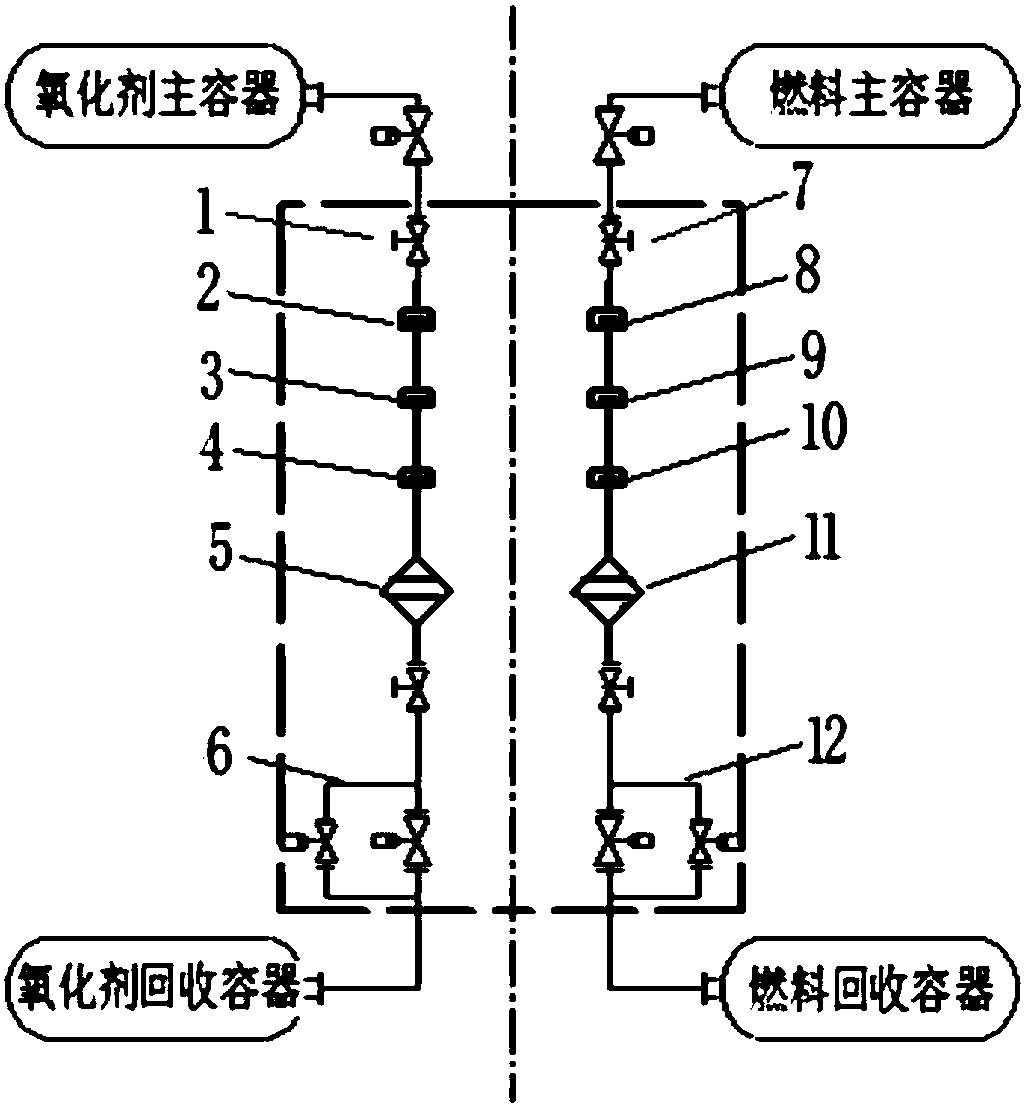
[0041] The composition principle of the test bench propellant flow field calibration system is as follows: figure 1 shown. Install a mass flowmeter in the main pipeline, configure the propellant recovery pipeline, and ensure that the position and state of the turbine flowmeter are consistent with those during the test run, and carry out the cold adjustment of the real propellant through the pressure adjustment control of the main propellant container calibration. The measurement principle of the mass flowmeter is the proportional relationship between the vibration frequency of the measuring tube inside the flowmeter and the mass flow rate of the fluid. Considering the continuity and consistency of the flow measurement state of the test bench and the influence of vibration and noise during the test run of the large engine, during the test run interval period, according to The number and frequency of test runs, regularly use the mass flowmeter to cool the real medium of the tur...


PUM


Abstract

The invention provides a liquid engine propellant flow field calibration system and method. The calibration result can be more precise and rapid, and high-precision measurement of the flow in an engine test is achieved. The conventional large liquid engine propellant flow field calibration system comprises a mass flow meter which is connected to a main pipeline in series and located between a propellant main vessel and a turbo flow meter, a pressure adjustment system and a propellant recycling pipeline are configured, and it is guaranteed that when the position and state of the turbo flow meter are consistent with those of test run, on the basis of the mass flow, a real propellant is adopted for conducting field calibration on the turbo flow meter; a propellant recycling pipeline is connected with the main pipeline in series and finally connected to a propellant recycling vessel, and the propellant recycling vessel is used for storing the propellant flowing in the exhaust process and the calibration process.

Description

technical field [0001] The invention belongs to the field of liquid rocket engine testing, and relates to a liquid engine propellant flow field calibration system and method. Background technique [0002] The propellant of a conventional liquid rocket engine is a two-component liquid medium of an oxidizer and a fuel, and the oxidant will burn when it contacts with the fuel, which is highly corrosive, highly toxic and dangerous. [0003] The propellant flow rate in liquid rocket engine test is a key parameter for assessing engine performance and must be measured accurately. [0004] The current conventional flow measurement method is to use a turbine flowmeter. The turbine flowmeter has the advantages of fast response and easy use. Its coefficient is calibrated with water in the metering department, and the accuracy meets the requirements of 0.5%. Installed on the actual application of the pipeline, due to the different physical properties of the fluid (viscosity and tempera...

Claims


Application Information

Patent Timeline
Patent Type & Authority Applications(China)
IPC IPC(8): G01F25/00
CPCG01F25/10
Inventor 潘思宇乔江晖陈海峰刘英元董冬彭飞白文义单琳姚羽佳耿直朱成亮
Owner XIAN AEROSPACE PROPULSION TESTING TECHN INST
Why Eureka
Try Eureka