
Control method for charging-and-discharging testing of battery and system thereof

A charge and discharge test and control method technology, applied in the direction of measuring electricity, measuring devices, measuring electrical variables, etc., can solve problems such as time-consuming and labor-intensive, not allowed to be carried on the plane, and threats to the health of operators

Pending Publication Date: 2018-04-20
SHANGHAI MROBOT TECH CO LTD
View PDF18 Cites 5 Cited by
  • Summary
  • Abstract
  • Description
  • Claims
  • Application Information

AI Technical Summary

Problems solved by technology

[0003] When producing these intelligent products, battery detection is a very important link. If the battery detection is not in place, the quality of the battery is not good enough, it is very likely to cause an explosion or generate sparks, and there is a great potential safety hazard
If some mobile terminals have battery problems, they are not even allowed to be carried on the plane, which brings great inconvenience to users
[0004] For a long time, batteries have been tested manually for charging and discharging. Due to the long battery charging and discharging cycle, manual operation is time-consuming and laborious; and the staff cannot continue to test the battery after get off work, resulting in low test efficiency.
Moreover, the voltage of some batteries is relatively high. Once a short circuit occurs during the test, a huge spark will be emitted, threatening the health of the operator.

Method used


Image

  • Control method for charging-and-discharging testing of battery and system thereof
  • Control method for charging-and-discharging testing of battery and system thereof
  • Control method for charging-and-discharging testing of battery and system thereof

Examples


Embodiment Construction

[0054] In order to more clearly illustrate the embodiments of the present invention or the technical solutions in the prior art, the specific implementation manners of the present invention will be described below with reference to the accompanying drawings. Obviously, the accompanying drawings in the following description are only some embodiments of the present invention, and those skilled in the art can obtain other accompanying drawings based on these drawings and obtain other implementations.

[0055] In order to make the drawing concise, each drawing only schematically shows the parts related to the present invention, and they do not represent the actual structure of the product. In addition, to make the drawings concise and easy to understand, in some drawings, only one of the components having the same structure or function is schematically shown, or only one of them is marked. Herein, "a" not only means "only one", but also means "more than one".

[0056] Such as f...


PUM


Abstract

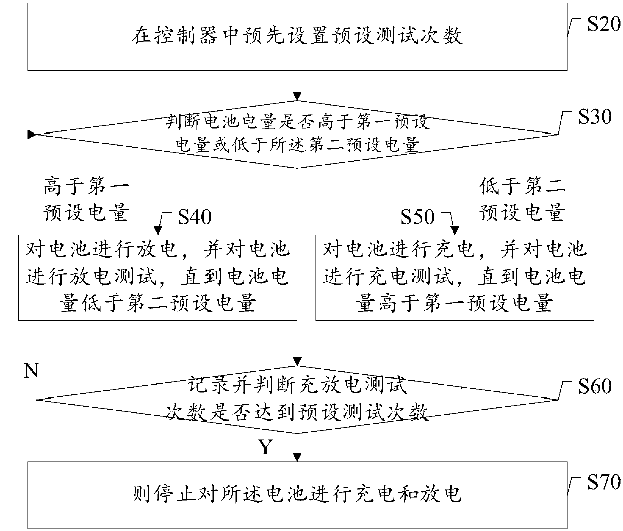
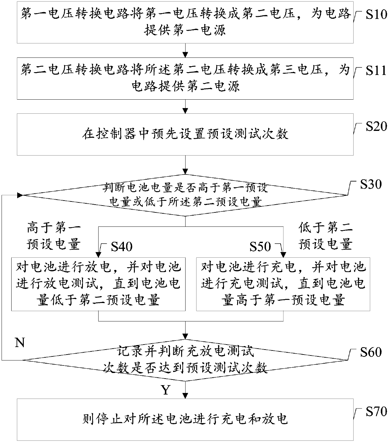
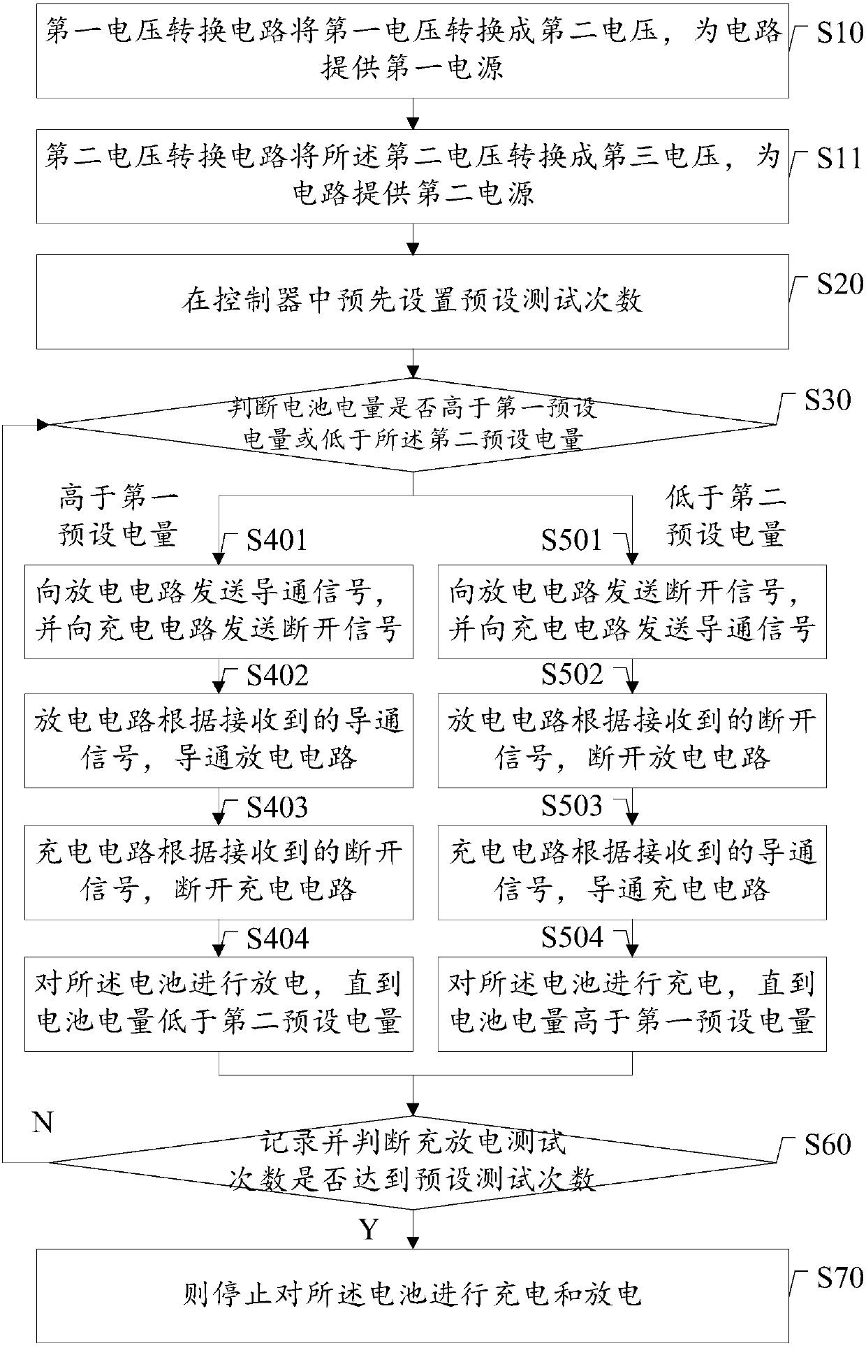
The invention provides a control method for charging-and-discharging testing of a battery and a system thereof. The control method comprises the steps of S20, setting a preset number of testing timesin a controller; S30, detecting the electric quantity of the battery, and determining whether the electric quantity of the battery is higher than a first preset electric quantity or lower than a second preset electric quantity; S40, when the controller detects a fact that the electric quantity is higher than the first electric quantity, performing discharging on the battery through a discharging circuit until the electric quantity of the battery is lower than the second preset electric quantity; S50, when the controller detects a fact that the electric quantity of the battery is lower than thesecond preset electric quantity, charging the battery through a charging circuit until the electric quantity of the battery is higher than the first preset electric quantity; S60, recording the number of charging-and-discharging testing times by the controller, and determining whether the number of charging-and-discharging testing times reaches a preset number of testing times; and S70, if yes, stopping charging and discharging to the battery; and otherwise, returning to the step S30. The control method and the system thereof have advantages of realizing automatic control for charging-and-discharging testing on the battery, saving manpower and improving testing efficiency.

Description

technical field [0001] The invention relates to battery testing, in particular to a control method and system for battery charging and discharging testing. Background technique [0002] With the advancement of science and technology, there are more and more intelligent products, ranging from mobile phones, computers, ipods, to robots and electric vehicles, which have brought surprises to our lives one after another. [0003] When producing these intelligent products, battery inspection is a very important link. If the battery inspection is not in place, the quality of the battery is not good enough, it is very likely to cause an explosion or generate sparks, which poses a great safety hazard. If some mobile terminals have battery problems, they are not even allowed to be carried on the plane, which brings great inconvenience to users. [0004] For a long time, batteries have been tested manually for charging and discharging. Due to the long battery charging and discharging ...

Claims


Application Information

Patent Timeline
Patent Type & Authority Applications(China)
IPC IPC(8): G01R31/36
CPCG01R31/385
Inventor 蒋化冰金铭鉴罗承雄谭舟梁兰徐志强严婷郦莉
Owner SHANGHAI MROBOT TECH CO LTD
Learn More