True-random-number generator based on autonomous boolean network structure
A Boolean network structure and true random number technology, applied in random number generators, logic circuits using basic logic circuit components, instruments, etc., can solve problems such as poor stability of entropy sources, achieve good randomness and increase uncertainty , the effect of improving the stability of the entropy source
- Summary
- Abstract
- Description
- Claims
- Application Information
AI Technical Summary
Problems solved by technology
Method used
Image
Examples
Embodiment 1
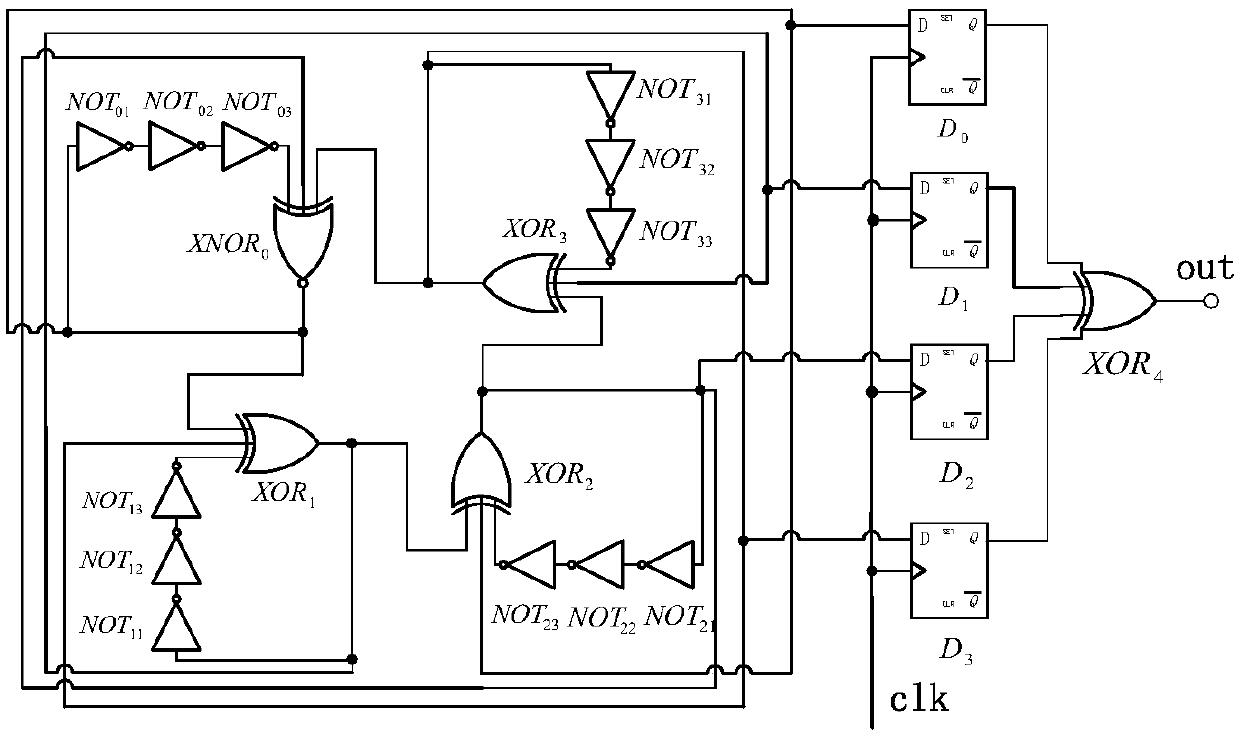
[0023] Embodiment 1. In this embodiment, the number of nodes in the oscillating circuit is 4, the number of inverters connected in series in the delay self-feedback is M=3, and the interval k=1;
[0024] refer to figure 2 , a true random number generator based on an autonomous Boolean network structure, including an oscillating circuit and a sampling circuit, where:
[0025] Oscillating circuit, a ring-shaped autonomous Boolean network structure composed of 4 logic gates as nodes, the 4 logic gates include 1 XNOR gate 0 and 3 XOR gates XOR 1 、XOR 2 、XOR 3 , each logic gate contains three input ports and one output port, where XNOR 0 The output port passes a time-delayed self-feedback circuit with XNOR 0 Any one of the input ports connected, XNOR 0 One of the remaining two input ports is XORed with 3 connected to the output port of the other with the XOR 2 The output ports are connected; XOR 1 The output port passes a time-delayed self-feedback circuit with an XOR 1 ...
Embodiment 2
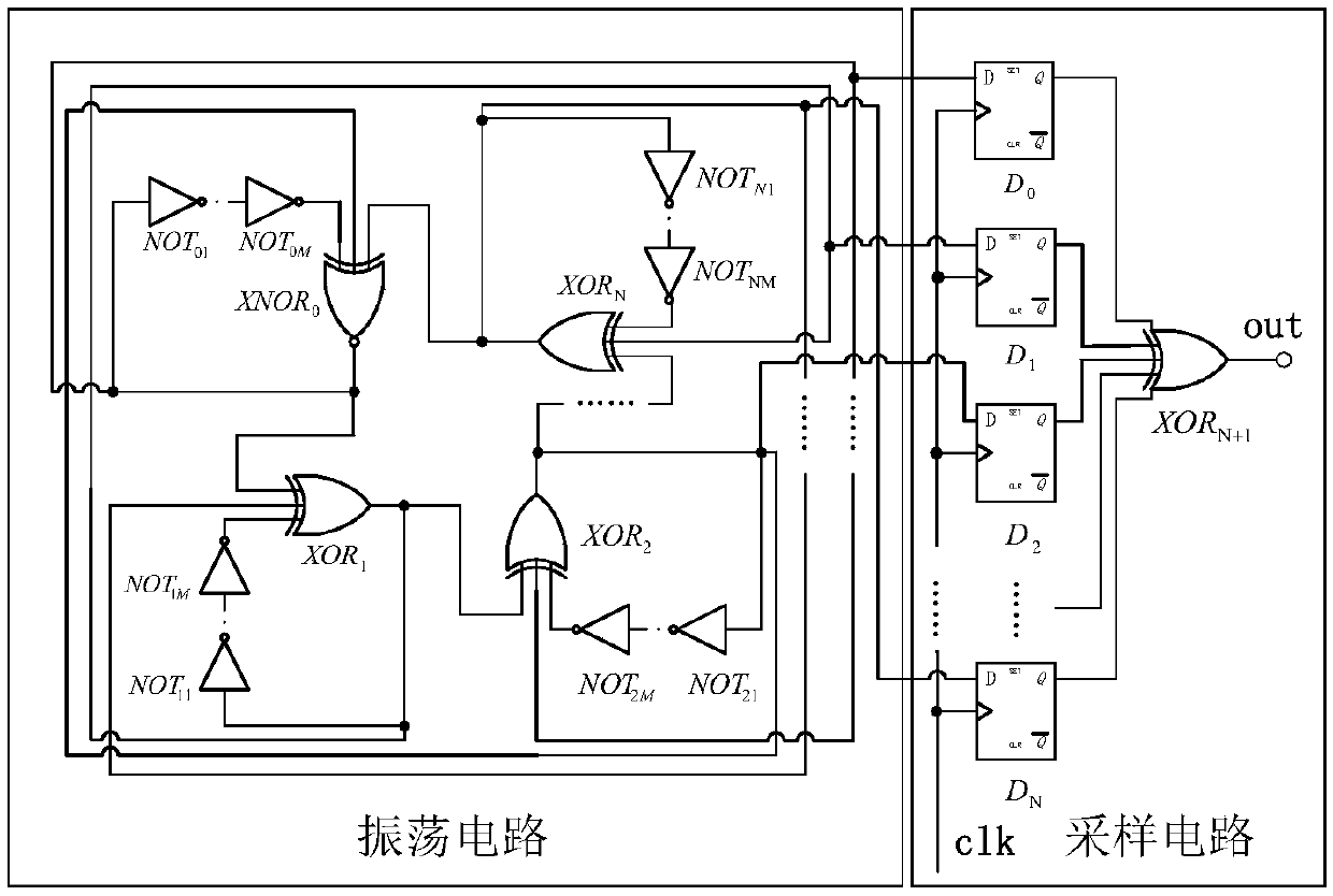
[0027] Embodiment 2, in this embodiment, the number of nodes in the oscillation circuit is 8, the number of inverters in the delay self-feedback is M=1, and the interval k=2;
[0028] A true random number generator based on an autonomous Boolean network structure, including an oscillating circuit and a sampling circuit, wherein:
[0029] Oscillating circuit, a ring-shaped autonomous Boolean network structure composed of 8 logic gates as nodes, the 8 logic gates include 1 XNOR gate 0 And 7 XOR gates XOR 1 、XOR 2 、XOR 3 、XOR 4 、XOR 5 、XOR 6 、XOR 7 , each logic gate contains three input ports and one output port, where XNOR 0 The output port with the inverter NOT 0 connected to the input port, the inverter NOT 0 The output port with XNOR 0 Any one of the input ports connected, XNOR 0 One of the remaining two input ports is XORed with 7 connected to the output port of the other with the XOR 3 The output ports are connected; XOR 1 The output port with the inverter NOT...
PUM
 Abstract
Description
Claims
Application Information
 - R&D
- Intellectual Property
- Life Sciences
- Materials
- Tech Scout
- Unparalleled Data Quality
- Higher Quality Content
- 60% Fewer Hallucinations
Browse by: Latest US Patents, China's latest patents, Technical Efficacy Thesaurus, Application Domain, Technology Topic, Popular Technical Reports.
© 2025 PatSnap. All rights reserved.Legal|Privacy policy|Modern Slavery Act Transparency Statement|Sitemap|About US| Contact US: help@patsnap.com


