
Current Collector

A technology of collector layer and conductive substrate, applied in the direction of structural parts, electrode carrier/collector, circuit, etc., can solve the problems of explosion, reduce the efficiency of battery electrochemical reaction, limit, etc., and achieve the effect of solving internal short circuit

Active Publication Date: 2018-04-20
PROLOGIUM TECH +1
View PDF4 Cites 8 Cited by
  • Summary
  • Abstract
  • Description
  • Claims
  • Application Information

AI Technical Summary

Problems solved by technology

[0002] For existing lithium batteries, the most difficult problem to solve is that during the electrochemical reaction inside the battery, because the collector layer (usually copper foil) of the negative electrode plate is approaching the state of lithium relative potential 0 volts Under the condition, the deposition and deposition reaction of lithium ions will continue on the surface of the collector layer, resulting in the formation of a large number of lithium synapses. The formation of lithium synapses not only consumes the amount of lithium ions inside the battery, but also makes the capacity cycle It gradually decreases after use, and because of the dendrite structure of the lithium synapse, it is easy to cause its sharp end to pierce the isolation layer. Once the structure of the isolation layer is damaged, it will cause an internal short circuit or even an explosion of the battery. situation
[0003] For the above bottleneck, one of the more common solutions is to use additives in the electrolyte, according to different additives, to reduce the probability of lithium ion deposition reaction, for example: reduce the activation energy of lithium ion formation passive layer (SEIlayer) reaction Make more lithium ions tend to form a passive layer without deposition reaction, or provide specific functional groups to generate lithium intermediates, so as to interfere with the deposition reaction of lithium ions. In addition, by using specific negative active materials, For example: Lithium Titanium Oxide (LTO), in order to prevent the negative electrode active material from being in the state of lithium relative potential 0 volts during the charging process, it can prevent lithium ions from depositing on the negative electrode plate. However, the above methods will Causes some obstacles to the deposition reaction of lithium ions, but the degree of influence is still limited, and in terms of the method of adding additives to the electrolyte, because the use of additives is usually accompanied by some side reactions, so although the deposition reaction is reduced Lithium ions, but some side reactions will reduce the efficiency of the electrochemical reaction inside the battery. In addition, when the active material of the negative plate is changed to lithium titanium oxide, because the potential of lithium titanium oxide is about 1.5 volts higher than that of lithium , when using the existing positive electrode material, the battery discharge voltage will be reduced to about 2.4V. Under the premise that the theoretical capacitance of lithium titanium oxide is equivalent to that of graphite, the energy density provided by the battery using lithium titanium oxide will be reduced. sacrifice

Method used


Image

  • Current Collector
  • Current Collector
  • Current Collector

Examples


Embodiment Construction

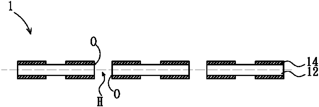
[0042] The spirit of the present invention is to provide a collector layer structure. The collector layer disclosed utilizes the insulating region therein to prevent electrons from contacting the surface close to the opening, so that lithium ions can be avoided during the electrochemical reaction. Deposition, reducing the penetration of lithium synapses through pores to puncture the isolation layer. The collector layer structure includes a conductive substrate and a plurality of insulating regions, wherein the conductive substrate has a plurality of holes, and each hole has two openings, and the insulating region is formed at least covering the periphery of the opening, and can also extend to the edge of the opening. Outside the periphery, and can also extend to at least part of the surface inside the hole, but at least part of the surface of the conductive substrate is exposed, which means that at least part of the surface of the conductive substrate is not covered by the insu...


PUM


Abstract

A current collector is disclosed in the present invention. The current collector comprises a conductive substrate and a plurality of isolation regions. The conductive substrate has a plurality of holes. Each hole has two openings. The isolation regions, which only partially cover the surface of the conductive substrate, are disposed at least on the areas nearby the peripheral surface of the openings. Due to the electrical insulation of the isolation regions formed nearby the peripheral surface of the openings, the lithium ions would not deposit centrally close to the openings of the holes during the electrical-chemical reaction of the battery. Accordingly, only few lithium dendrites are formed inside the holes and grow towards the separator so that the position and the amount of the formation of the lithium dendrite can be effectively controlled. Thus, the safety of the battery can be greatly improved.

Description

technical field [0001] The present invention relates to a collector layer and an applied electrode plate thereof, in particular to a collector layer with an insulating region, and generally used as a collector layer structure of a negative electrode layer. Background technique [0002] For existing lithium batteries, the most difficult problem to solve is that during the electrochemical reaction inside the battery, because the collector layer (usually copper foil) of the negative electrode plate is approaching the state of lithium relative potential 0 volts Under the condition, the deposition and deposition reaction of lithium ions will continue on the surface of the collector layer, resulting in the formation of a large number of lithium synapses. The formation of lithium synapses not only consumes the amount of lithium ions inside the battery, but also makes the capacity cycle It gradually decreases after use, and because of the dendrite structure of the lithium synapse, i...

Claims


Application Information

Patent Timeline
Patent Type & Authority Applications(China)
IPC IPC(8): H01M4/80H01M10/0525
CPCH01M4/80H01M10/0525H01M4/134H01M4/382H01M4/661H01M4/663H01M4/664H01M4/667H01M10/052Y02E60/10
Inventor 杨思枬
Owner PROLOGIUM TECH
Learn More