
Microstrip antenna RFID label-based array strain sensor

An RFID tag and strain sensor technology, which is applied to antennas, antenna parts, antenna grounding devices, etc., can solve the problems of complex monitoring structure, inability to guarantee accuracy, time-consuming and labor-intensive, etc.

Inactive Publication Date: 2018-04-20
BEIJING UNIV OF TECH
View PDF5 Cites 19 Cited by
  • Summary
  • Abstract
  • Description
  • Claims
  • Application Information

AI Technical Summary

Problems solved by technology

The current detection methods for the surface defects of fan blades include tapping on the ground to distinguish sound, observing with a telescope, and dismantling them for offline detection, which is time-consuming and labor-intensive, and the accuracy cannot be guaranteed.
[0003] In order to overcome the shortcomings of traditional monitoring structure complex, this paper combines radio frequency identification (Radio Frequency Identification, RFID) technology with sensor technology, and proposes an array strain sensor based on microstrip antenna RFID tags, which reduces costs and improves detection distance. The health monitoring of fan structure is of great significance

Method used


Image

  • Microstrip antenna RFID label-based array strain sensor
  • Microstrip antenna RFID label-based array strain sensor
  • Microstrip antenna RFID label-based array strain sensor

Examples


Embodiment Construction

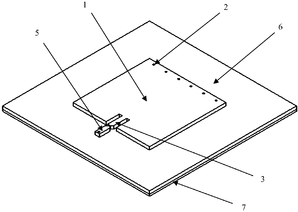
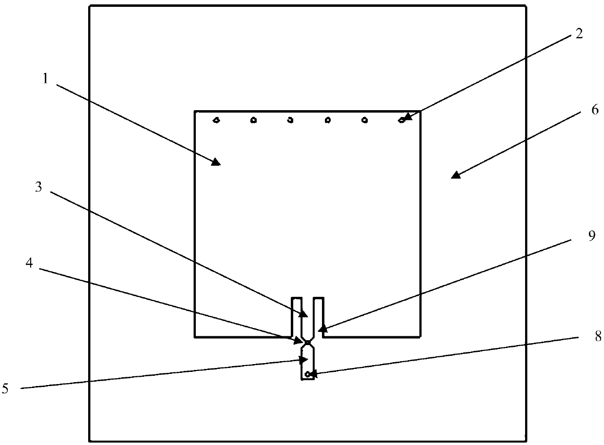
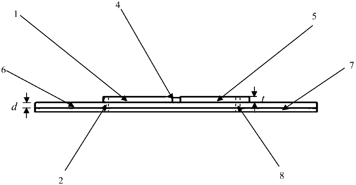
[0017] Such as Figure 1-5 As shown, the material of the dielectric base layer (6) is Rogers high-frequency board, the dielectric constant is 2.2, and the two conductor layers on the sensor include the metal radiation surface (1), the short-circuit wall (2), the first feeder (3), and the chip (4), the second feeder (5), the dielectric base layer (6), the metal base plate (7), and the short-circuit hole (8) all use copper foil as the material, and the main parameter dimensions of the sensor are shown in Table 1 below:

[0018] Table 1 sensor size parameter table

[0019]

[0020]

[0021] The tag antenna is designed in the form of a microstrip antenna to receive the energy from the reader, the energy is transmitted to the tag chip and activates the sensor (the minimum energy to activate the sensor is called the activation threshold of the tag sensor), when the tag antenna is at the resonant frequency , the sensor has the highest energy receiving efficiency, so the activa...


PUM

PropertyMeasurementUnit
Lengthaaaaaaaaaa
Widthaaaaaaaaaa
Thicknessaaaaaaaaaa

Abstract

The invention discloses a microstrip antenna RFID label-based array strain sensor. When the microstrip antenna RFID label-based array strain sensor is used as a novel detection technology of a passiveantenna and applied to draught fan blade strain detection, the defect of complexity of a traditional monitoring structure is overcome, the microstrip antenna RFID label-based array strain sensor is low in cost, the detection distance is extended, the interference to an environment is reduced, the detection range is expanded, and the microstrip antenna RFID label-based array strain sensor has important significance to health monitoring of a draught fan blade structure. The label sensor comprises a label antenna and a label chip and is characterized in that the label antenna comprises a metal radiation surface, a dielectric base layer and a metal grounding layer, wherein one end of the label is a radiation end, the other end of the label is a matching end, and structure strain monitoring isachieved by a relation between offset and strain of a label resonant frequency; since unique label information exists in each label chip, a reader can simultaneously read a plurality of label information; and a plurality of labels are buried in a draught fan blade and are arranged in an array way, large-area stress monitoring is achieved, and the function of the sensor is achieved.

Description

technical field [0001] The invention belongs to the field of structural health monitoring technology and antenna technology, and designs an array strain sensor based on a microstrip antenna type RFID tag. Background technique [0002] Wind energy is one of the pollution-free energy sources, and it is also a renewable energy type. As the main equipment for converting wind energy into electrical energy, the smooth operation of wind turbines is closely related to production safety. Therefore, the monitoring of fan blades is also very important. The reason for the failure of the blades of wind turbines is that the wind turbines will bear loads during operation. When the load reaches the strength limit that the blade structure can bear, the blades will crack until they break. The current detection methods for the surface defects of wind turbine blades include knocking on the ground to distinguish sound, telescope observation, and dismantling them for offline detection, which is...

Claims


Application Information

Patent Timeline
IPC IPC(8): H01Q1/38H01Q1/48H01Q1/22G06K17/00G01N27/26
CPCH01Q1/38G01N27/26G06K17/00H01Q1/2225H01Q1/48
Inventor 宋国荣文硕吕炎张斌鹏窦致夏何存富
Owner BEIJING UNIV OF TECH
Learn More