A Timing Protection Circuit for Controlling Depletion Mode Power Devices

A technology for power devices and protection circuits, which is applied in the electronic field and can solve problems such as burnout of depletion-type power devices and damage to reverse-phase proportional operation circuits.

Active Publication Date: 2021-07-02
TIME VARYING TRANSMISSION CO LTD
View PDF0 Cites 0 Cited by
  • Summary
  • Abstract
  • Description
  • Claims
  • Application Information

AI Technical Summary

Problems solved by technology

[0009] The invention provides a timing protection circuit for controlling depletion-type power devices, which solves the technical problem in the prior art that the inverse proportional operation circuit is damaged or the grid voltage is not suitable, which will cause the depletion-type power devices to burn out

Method used


Image

  • A Timing Protection Circuit for Controlling Depletion Mode Power Devices
  • A Timing Protection Circuit for Controlling Depletion Mode Power Devices
  • A Timing Protection Circuit for Controlling Depletion Mode Power Devices

Examples


Embodiment Construction

[0035] The invention provides a sequential protection circuit for controlling the depletion power device, which solves the technical problem in the prior art that the inverse proportional operation circuit is damaged or the gate voltage is not suitable to cause the depletion power device to burn out.

[0036] In order to make the purpose, features and advantages of the present invention more obvious and understandable, the technical solutions in the embodiments of the present invention will be clearly and completely described below in conjunction with the accompanying drawings in the embodiments of the present invention. Obviously, the following The described embodiments are only some, not all, embodiments of the present invention. Based on the embodiments of the present invention, all other embodiments obtained by persons of ordinary skill in the art without making creative efforts belong to the protection scope of the present invention.

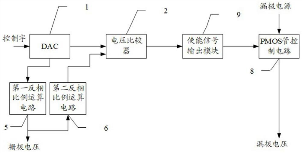
[0037] see figure 2 , a structural...


PUM


Abstract

The invention discloses a timing protection circuit for controlling depletion-type power devices, comprising: DAC, a first inverse proportional operation circuit, a second inverse proportional operation circuit, a voltage comparator, an enable signal output module and a PMOS tube control circuit; the DAC includes a first voltage output terminal and a second voltage output terminal; the first terminal of the first inverse proportional operation circuit is connected to the first voltage output terminal, and the second terminal of the first inverse proportional operation circuit is used as the gate voltage output terminal; the second terminal of the first inverse proportional operation circuit is connected to the negative input voltage terminal of the voltage comparator with a second inverse proportional operation circuit; the positive input voltage terminal of the voltage comparator is connected to the second voltage output terminal; The enable signal output module is used to output the enable signal to the PMOS transistor control circuit when the voltage comparator outputs a low level. It solves the technical problem in the prior art that the damage of the inverse proportional operation circuit or the improper gate voltage will cause the burnout of the depletion power device.

Description

technical field [0001] The invention relates to the field of electronic technology, in particular to a sequential protection circuit for controlling depletion-type power devices. Background technique [0002] With the commercialization of 4G communication standards, the design requirements for power amplifiers are becoming more and more stringent. In power amplifiers, depletion-type power devices are often used. Depletion-type power devices are generally field effect transistors, which have three poles, which are Gate, Source, and drain. In essence, it belongs to a voltage-controlled current-type device (the gate voltage controls whether the drain can be turned on), and the turn-on voltage of the depletion-type power device is a negative voltage. Common depletion-mode power devices include GaAs devices and GaN devices. [0003] When depletion-mode power devices are used, it is necessary to strictly abide by the order of gate first and then drain, otherwise it may be perman...

Claims


Application Information

Patent Timeline
Patent Type & Authority Patents(China)
IPC IPC(8): H03F1/52H03K17/687
CPCH03F1/523H03K17/687
Inventor 黄敬滨刘耿烨李跃星
Owner TIME VARYING TRANSMISSION CO LTD
Why Eureka
Try Eureka