Automatic cutting-off device and cutting-off process for aluminum flat tube

An automatic cutting and cutting device technology, applied in the direction of manufacturing tools, other manufacturing equipment/tools, etc., can solve the problems of inability to ensure that the position of the cutting knife corresponds to the center line of the shrinkage of the aluminum flat tube, the length of the shrinkage, the depth of the shrinkage, the condenser Problems such as assembly and use impact, to achieve the effect of convenient batch assembly, low equipment investment cost, and improving product competitiveness

Active Publication Date: 2018-04-24
张家港市宏基精密铝材科技有限公司
View PDF8 Cites 9 Cited by
  • Summary
  • Abstract
  • Description
  • Claims
  • Application Information

AI Technical Summary

Problems solved by technology

The disadvantage of the prior art is that the various devices of the cutting equipment need to be closely matched, and the accuracy of the size and time control is high. The existing cutting equipment will decrease in precision under long-term operation, resulting in dimensional deviation of the aluminum flat tube. ;The jitter of each device during operation will drive the aluminum flat tube to swing, and it is impossible to ensure that the cutter corresponds to the center line of the shrinkage of the aluminum flat tube during cutting, resulting in inconsistent length and depth of the shrinkage on both sides of the product after cutting, that is, the shape appears Deviation, which affects the assembly and use of the condenser

Method used


Image

  • Automatic cutting-off device and cutting-off process for aluminum flat tube
  • Automatic cutting-off device and cutting-off process for aluminum flat tube

Examples


Embodiment Construction

[0027] In order to make the object, technical solution and advantages of the present invention clearer, the present invention will be further described in detail below in conjunction with the accompanying drawings and embodiments. It should be understood that the specific embodiments described here are only used to explain the present invention, not to limit the present invention.

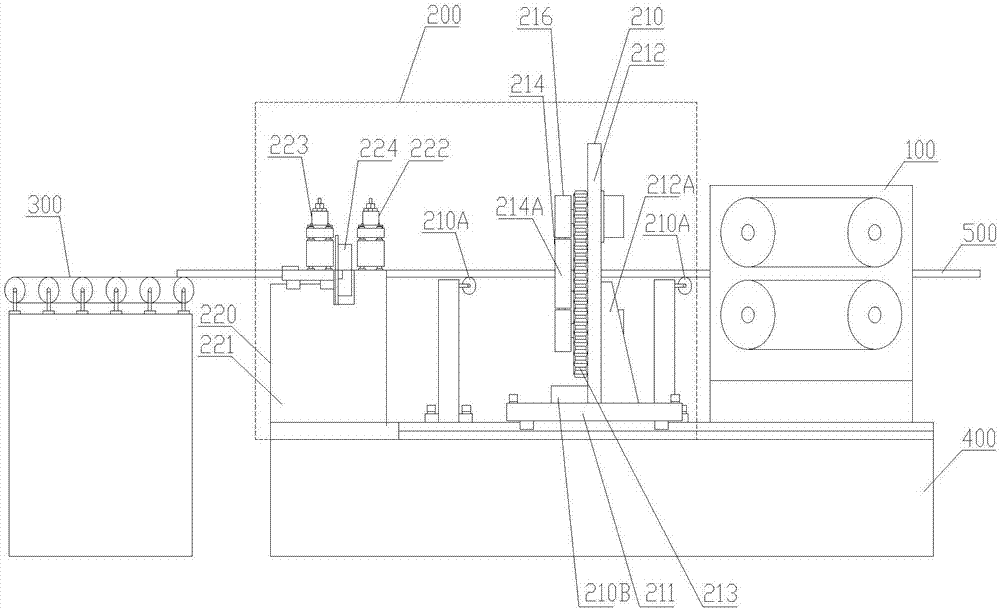
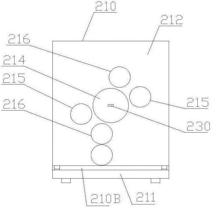
[0028] Such as figure 1 , 2As shown, the automatic cutting device for aluminum flat tubes includes a feeding device, a pressing device, a correcting device, a sizing feeding device 100, a cutting device 200 and a collecting device 300, a correcting device, and a sizing feeding device 100 arranged in sequence from right to left. And the cutting device 200 is installed on the general base 400, and the sizing feeding device 100 is driven by a servo motor. It is characterized in that the cutting device 200 includes a necking cutting device 210 and a notch breaking device 220. The left side of the dev...


PUM


Abstract

The invention discloses an automatic cutting-off device and a cutting-off process for an aluminum flat tube. The automatic cutting-off device comprises a cutting-off device body, wherein the cutting-off device body comprises a necking cutting device and a notch pulling-off device; the necking cutting device comprises a first base, a assembly fixing plate, a driving mechanism, a central connectinggear, a necking knife assembly and a bisection knife assembly, wherein the assembly fixing plate is fixed on the first base, the central connecting gear, the necking knife assembly, the bisection knife assembly and the driving mechanism are installed on the assembly fixing plate; and the notch pulling-off device comprises a second base, a locking device and a pulling-off device body, wherein the locking device is fixedly installed at the right end of the second base, a transverse sliding rail is arranged at the left end of the second base, a transverse sliding groove is formed in the bottom part of the pulling-off device, and the second base is in sliding connection with the pulling-off device. The cutting-off process determined by the device comprises the following steps of conveying, necking and cutting, conveying to the notch pulling-off device, pulling-off, conveying and collecting. The cutting-off device and the cutting-off process have the advantages that structure is simple, operation is stable, operation is convenient, and size deviation caused by shaking of the device is overcome, and the precision is high.

Description

technical field [0001] The invention belongs to the technical field of aluminum flat tube production equipment, and in particular relates to an automatic aluminum flat tube cutting device and a cutting process. Background technique [0002] As a new type of environmentally friendly refrigerant bearing pipe component, aluminum flat tubes are assembled and welded with headers for condensers in automobiles, household air conditioners, and ships, and play a considerable role in temperature regulation. The end of the aluminum flat tube is usually necked, and the condenser is assembled with the necked end as a reference. The aluminum flat tube automatic cutting equipment used in the production of aluminum flat tubes in the prior art includes a feeding device, a pressing device, a correction device, a sizing feeding device, a cutting device and a collecting device, wherein the cutting device includes a necking device and a cutting puller. The breaking device is the most critical e...

Claims


Application Information

Patent Timeline
Patent Type & Authority Applications(China)
IPC IPC(8): B23P23/04B23P23/06B23P15/00
CPCB23P15/00B23P23/04B23P23/06Y02P70/10
Inventor 樊志贤梅朝
Owner 张家港市宏基精密铝材科技有限公司
Why Eureka
Try Eureka