Robot paw clamp with flexible clamping and fixing function

A technology of fixed function and robot hand, which is applied in the direction of manipulators, chucks, manufacturing tools, etc., can solve the problems of affecting the grasping work, vacuum suction cup loss, and limiting the scope of use, so as to achieve strong product adaptability, avoid suction cup loss, and avoid The effect of box drop accidents

Pending Publication Date: 2018-04-24
云南柔控科技有限公司
View PDF4 Cites 7 Cited by
  • Summary
  • Abstract
  • Description
  • Claims
  • Application Information

AI Technical Summary

Problems solved by technology

[0003] Under normal circumstances, in order to prevent the vacuum degree from weakening, the object moving at a high speed, or the vacuum from being accidentally disconnected from falling when grabbing and handling items such as boxes, the structure of clamping on both sides or the bottom of the bottom is usually combined with the suction cup. , but when clamping on both sides, if the box is not in the middle of the gripper, the box will be displaced during clamping, causing greater friction between the box and the vacuum suction cup, resulting in loss of the vacuum suction cup and is very likely A gap will be created between the suction cup and the clamped box, destroying the vacuum, and thus affecting the entire grabbing work; and the use of the bottom pocket structure will not only cause a large vertical height, but also cause inconvenience to the more compact shelves, which restricts its use. range; in addition, the bottom structure generally uses pallets to hold materials from below and clamp objects from above. Due to the existence of pallets at the bottom and the connection structure at the side, the goods can only be grasped sequentially from the side inward, resulting in It cannot be grabbed from the top arbitrarily as needed, which also limits the scope of use
In addition, for the vacuum chucks in the prior art, for objects that are not planar, a special vacuum chuck with a corresponding structure must be selected according to the surface structure and contour of the workpiece, which cannot be applied to the needs of customers for packaging shapes, packaging materials, and cost savings.

Method used


Image

  • Robot paw clamp with flexible clamping and fixing function
  • Robot paw clamp with flexible clamping and fixing function
  • Robot paw clamp with flexible clamping and fixing function

Examples


Embodiment Construction

[0019] The present invention will be further described below in conjunction with the accompanying drawings and examples, but the present invention is not limited in any way. Any changes or improvements made based on the teaching of the present invention belong to the protection scope of the present invention.

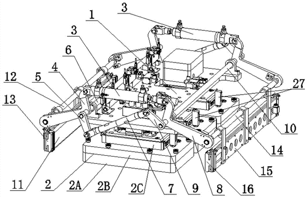
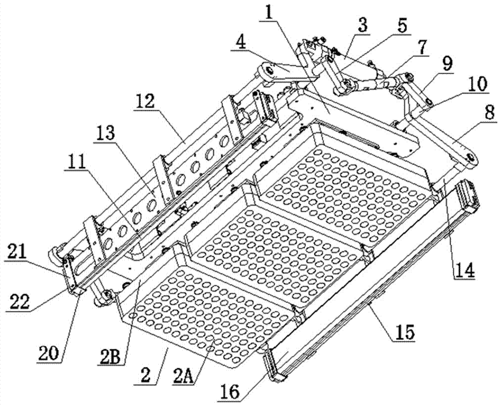
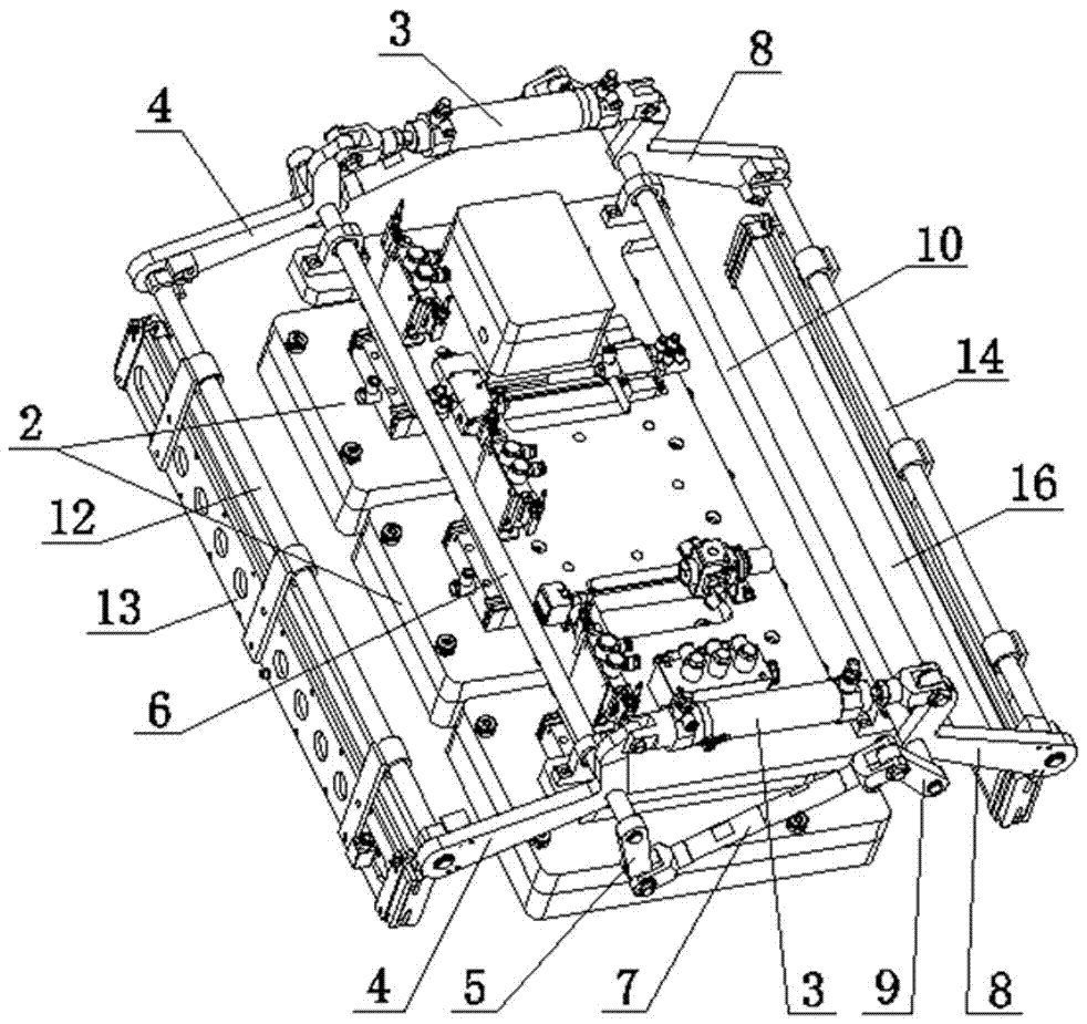
[0020] like Figures 1 to 5 As shown, the present invention includes a mounting plate 1, a sucker device 2, a linear drive device 3, a left connecting rod 4, a left connecting plate 5, a left connecting shaft 6, a pull rod 7, a right connecting rod 8, a right connecting plate 9, and a right connecting shaft 10. Left clamping airbag 11, left airbag shaft 12, left airbag plate 13, right airbag shaft 14, right airbag plate 15, the bottom of the mounting plate 1 is connected with a sucker device 2 with the working face down, and the mounting plate 1 The top is respectively connected with a left connecting shaft 6 and a right connecting shaft 10 in parallel rotation. Fixedl...


PUM


Abstract

The invention discloses a robot paw clamp with flexible clamping and fixing functions. The bottom of a mounting plate is connected with a sucker device whose working surface is downward. The top of the mounting plate is parallelly screwed with a left connecting shaft and a right connecting shaft. Two ends of the left connecting shaft are respectively vertically and fixedly connected with the middle parts of two parallel left connecting rods, and are respectively vertically and fixedly connected with ends of left connecting plates. Two ends of the right connecting shaft are respectively vertically and fixedly connected with the middle parts of two right connecting rods, and are vertically and fixedly connected with ends of right connecting plates. Top ends of the left connecting rod and theright connecting rod are respectively hinged with two ends of a linear driving device. The other ends of the left connecting plates and the right connecting plates are hinged with pull rods. A left air bag shaft which is parallel with the left connecting shaft is arranged between the bottom ends of the two left connecting rods. One side of the left air bag plate is fixedly connected with the leftair bag shaft, and one surface is fixedly provided with a left clamping air bag. A right air bag shaft which is parallel with the right connecting shaft is arranged between the bottom ends of the tworight connecting rods. One side of the right air bag plate is fixedly connected with the right air bag shaft, and is parallel with the left air bag plate. The robot paw clamp is characterized by compact structure, stable and reliable clamping, good adaptive capacity, and accurate positioning.

Description

technical field [0001] The invention belongs to the technical field of industrial robots, and in particular relates to a robot gripper clamp with flexible clamping and fixing functions, which has the advantages of compact structure, stable and reliable clamping, strong adaptability and precise positioning. Background technique [0002] With the improvement of mechatronics technology, more and more robots are used in modern warehousing, logistics and packaging lines to complete unstacking, palletizing and handling operations according to given procedures, trajectories and requirements. Especially in harsh environments such as high temperature, high pressure, dusty, flammable, explosive, and radioactive, as well as heavy, monotonous, and frequent operations, robots are used to replace humans to complete operations, which has the advantages of safety, reliability, high efficiency, and low cost. The handling robots in the prior art generally use general-purpose robots combined w...

Claims


Application Information

Patent Timeline
Patent Type & Authority Applications(China)
IPC IPC(8): B25J15/00B25J15/06
CPCB25J15/0023B25J15/0683
Inventor 杨灏泉郭红英李亚平李文鹏徐勤坤
Owner 云南柔控科技有限公司
Why Eureka
Try Eureka