Vibration impacting device

A technology of jars and impact chambers, which is applied in drilling equipment, earthwork drilling, driving devices for drilling in boreholes, etc., and can solve the problems of general speed-up effect of PDC bits and unstable torque of PDC bits, etc.

Pending Publication Date: 2018-04-24
穆总结
View PDF6 Cites 7 Cited by
  • Summary
  • Abstract
  • Description
  • Claims
  • Application Information

AI Technical Summary

Problems solved by technology

[0004] The purpose of the present invention is to provide a vibrator, which solves the technical problem that the torque of the PDC bit is not constant in the prior art, which leads to the general effect of PDC bit speed increase

Method used


Image

  • Vibration impacting device
  • Vibration impacting device
  • Vibration impacting device

Examples


Embodiment Construction

[0048] The technical solutions of the present invention will be further described below in conjunction with the accompanying drawings and through specific implementation methods.

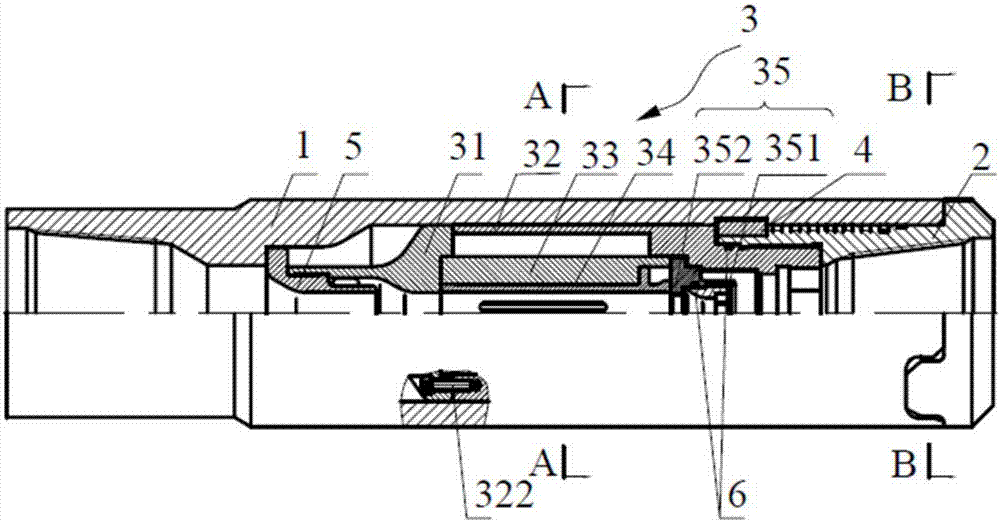
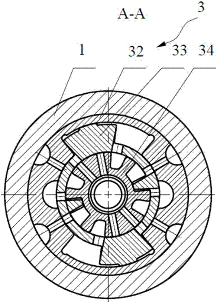
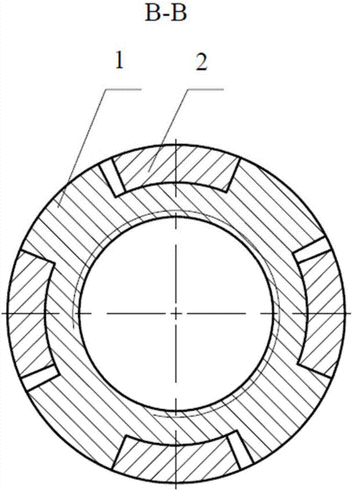
[0049] This embodiment provides a vibrator, such as Figure 1-3 As shown, the jar includes an outer cylinder 1, a lower joint 2, a rotating assembly 3 and a fixed assembly 4 arranged inside the outer cylinder 1, the fixed assembly 4 is arranged between the rotating assembly 3 and the lower joint 2, and the lower joint 2 is respectively Connected to the outer cylinder 1 and the rotating assembly 3. Wherein, the rotating assembly 3 includes a connecting piece 31, an impact chamber 32 connected to the connecting piece 31, an impact hammer 33 disposed inside the impact chamber 32, a switch valve 34 disposed inside the impact hammer 33 and abutting against the impact chamber. The throttling assembly 35 on the inner wall of 32, the impact hammer 33 and the switching valve 34 are arranged between the connec...


PUM


Abstract

The invention belongs to the technical field of well drilling, and discloses a vibration impacting device. The vibration impacting device includes an outer cylinder, a lower connector and a rotating assembly and a fixing assembly which are arranged inside the outer cylinder, the fixing assembly is arranged between the rotating assembly and the lower connector, and the lower connector is connectedwith the outer cylinder and the rotating assembly separately. The rotating assembly includes a connecting piece, an impacting cavity connected to the connecting piece, an impacting hammer arranged inside the impacting cavity, a change-over valve arranged inside the impacting hammer, and a throttle assembly which abuts against the inner wall of the impacting cavity, and the impacting hammer and thechange-over valve are arranged between the connecting piece and the throttle assembly. The connecting piece, the impacting cavity, the impacting hammer, the change-over valve and the throttle nozzleare all of a hollow structure and communicated with one another. The lower connector is connected to the impacting cavity, both the impacting hammer and the change-over valve can rotate in the circumferential direction in a reciprocating mode, the impacting cavity can limit the impacting hammer, the impacting hammer can limit the change-over valve, and therefore it is ensured that torque which a PDC drill bit is subjected to is constant.

Description

technical field [0001] The invention relates to the technical field of increasing the speed of drilling tools, in particular to a jar. Background technique [0002] Drilling speed increase is an eternal theme in the drilling industry. As the current international oil price continues to rise, increasing drilling speed has become one of the main means for major oilfields to reduce costs and increase efficiency in the process of exploration and development. [0003] In terms of improving the mechanical drilling speed, with the continuous deepening of research, domestic and foreign researchers have gradually discovered that to fundamentally improve the speed-up effect of the PDC bit, it is necessary to start with ensuring the stability of the PDC bit, that is, to ensure that the PDC bit is used in rock-breaking drilling. Keep the torque constant during the process. When the PDC bit is cutting and breaking the rock, the cutting teeth will fail to break the rock instantly. At th...

Claims


Application Information

Patent Timeline
Patent Type & Authority Applications(China)
IPC IPC(8): E21B4/14E21B10/42E21B10/60E21B17/042
CPCE21B4/14E21B10/42E21B10/60E21B17/042
Inventor 穆总结
Owner 穆总结
Why Eureka
Try Eureka