Flared tube and joint tightening machine

The technology of a flared pipe and a tightening machine is applied in the field of flared pipes, and can solve the problems of manual tightening torque, tightening force and tightening angle not up to the standard, high requirements for matching the inner cone surface of the flared pipe, and large manual tightening force. Achieve the effect of reducing work intensity, avoiding occupational diseases, and speeding up tightening speed

Pending Publication Date: 2021-02-23
HAITIAN PLASTICS MACHINERY GRP
View PDF5 Cites 1 Cited by
  • Summary
  • Abstract
  • Description
  • Claims
  • Application Information

AI Technical Summary

Problems solved by technology

[0003] There are problems in the prior art: one is that the diameter of the flaring pipe is 42mm, and the opposite sides of the joint and the nut are 55mm and 60mm respectively, so the manual tightening force is relatively large, and the labor intensity of pure manual screwing is high and the effici

Method used


Image

  • Flared tube and joint tightening machine
  • Flared tube and joint tightening machine
  • Flared tube and joint tightening machine

Examples


Embodiment Construction

[0028] The following are specific embodiments of the present invention and in conjunction with the accompanying drawings, the technical solutions of the present invention are further described, but the invention is not limited to these embodiments.

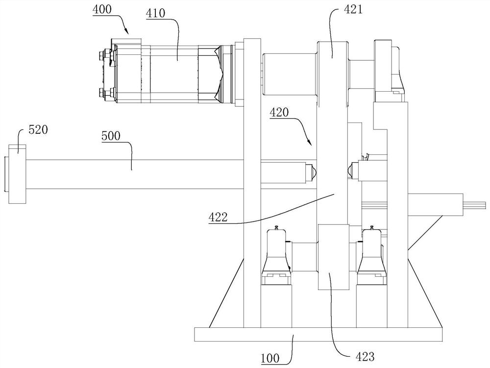
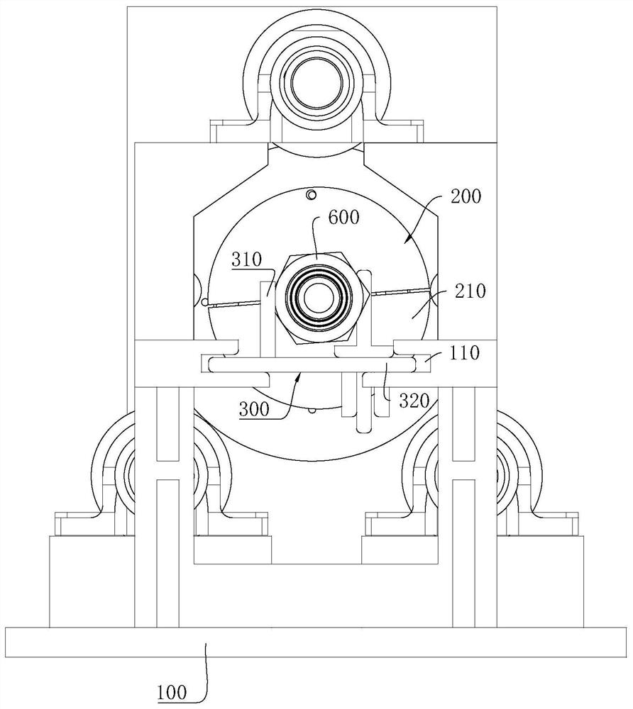
[0029] Such as Figure 1-4 As shown, a flared pipe joint tightening machine includes:

[0030] The support 100, the support 100 is used to provide support for other components.

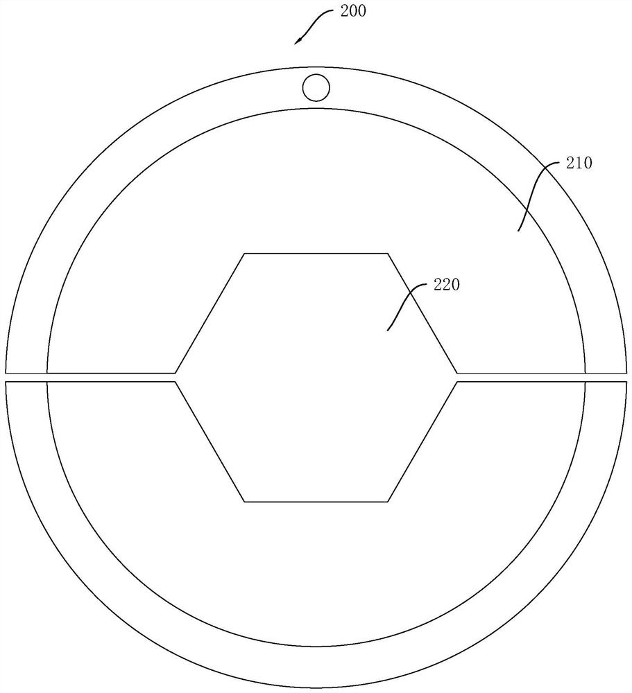
[0031] The nut clamping mechanism 200 is arranged on the support 100, and one end of the flared tube 500 is provided with a nut 510 stuck in the nut clamping mechanism 200, and the other end of the flared tube 500 is provided with a square flange 520, and the nut clamps The tightening mechanism 200 is used to clamp the nut 510 and drive the nut 510 to rotate.

[0032] The joint clamping mechanism 300 is slidably arranged on the support 100 and is used to fix the joint 600. When the joint clamping mechanism 300 slides to a preset position, the joint 600 ...


PUM


Abstract

The invention discloses a flared tube and joint tightening machine. The problems that the mode of manually tightening a flared tube and a joint is high in labor intensity, high in rejection rate and low in assembly efficiency in the prior art are solved. The flared tube and joint tightening machine comprises a support seat, a nut clamping mechanism, a joint clamping mechanism and a power mechanism; a nut at one end of the flared pipe is fixed through the nut clamping mechanism,the joint is fixed through the connector clamping mechanism, thus, the joint cannot rotate and can move in the radialdirection along with the nut, and the power mechanism is arranged to drive the nut clamping device to rotate and further drive the nut to rotate, and the nut and the joint are tightened; when the nuttightening pressure reaches a preset value, the power mechanism stops working, the nut does not continue to be tightened any more, semi-automatic tightening of the flared tube and the joint can be achieved, the workload of an operator can be reduced, the assembly efficiency can be improved, the assembly quality can be guaranteed, and the cost is reduced.

Description

technical field [0001] The invention relates to the technical field of flared pipes, in particular to a flared pipe joint tightening machine. Background technique [0002] The structure of the tightening of the flared steel pipe joint is that the outer tapered surface of the joint and the inner tapered surface of the flared pipe are in contact with each other, and the inner and outer tapered surfaces are pressed into contact by rotating the nut on the flared pipe. Therefore, it is not possible to use ordinary air tools to turn the joint to tighten the flared pipe joint. At present, the joint is fixed at one end, and the other end is manually tightened with an open end wrench on the booster rod. It requires high experience and physical strength for operators. [0003] There are problems in the prior art: one is that the diameter of the flaring pipe is 42 mm, and the opposite sides of the joint and the nut are 55 mm and 60 mm, respectively, so the manual tightening force is ...

Claims


Application Information

Patent Timeline
IPC IPC(8): B23P19/06
CPCB23P19/06
Inventor 徐立超徐小明贺嘉贝
Owner HAITIAN PLASTICS MACHINERY GRP
Why Eureka
Try Eureka