
Tunnel assembly for wind driven generator testing

A technology for wind turbines and tunnels, which is used in the monitoring of wind turbines, wind turbines, components of pumping devices for elastic fluids, etc. Long and other problems, to achieve the effect of simple structure, extended service life, simple and easy loading and unloading

Pending Publication Date: 2018-04-24
NANJING HIGH DRIVE ELECTROMECHANICAL AUTOMATION EQUIP CO LTD
View PDF5 Cites 0 Cited by
  • Summary
  • Abstract
  • Description
  • Claims
  • Application Information

AI Technical Summary

Problems solved by technology

[0002] Most of the existing test tunnels used for testing generators have an integral structure. The test tunnels are long and occupy a large space, and the existing wind turbine test tunnels cannot adjust the size of the tunnel air outlet. If you want to change the wind The flow rate can only be achieved by changing the power of the blower. Using a high-power blower consumes a lot of power, and when replacing a different blower, the tunnel needs to be disassembled, which is very cumbersome to use
In addition, when the fan in the existing test tunnel is working, the vibration generated by the fan is directly transmitted to the tunnel. If things go on like this, it will cause wear at the junction of the tunnel and damage the tunnel

Method used


Image

  • Tunnel assembly for wind driven generator testing
  • Tunnel assembly for wind driven generator testing
  • Tunnel assembly for wind driven generator testing

Examples


Embodiment Construction

[0024] The present invention will be further described below in conjunction with the accompanying drawings.

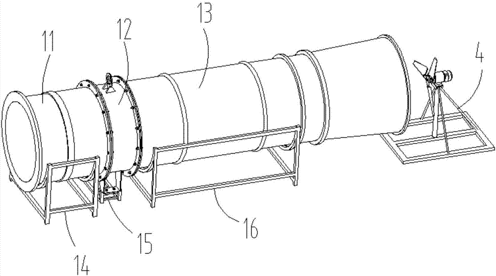
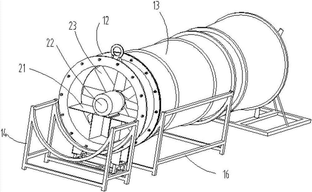
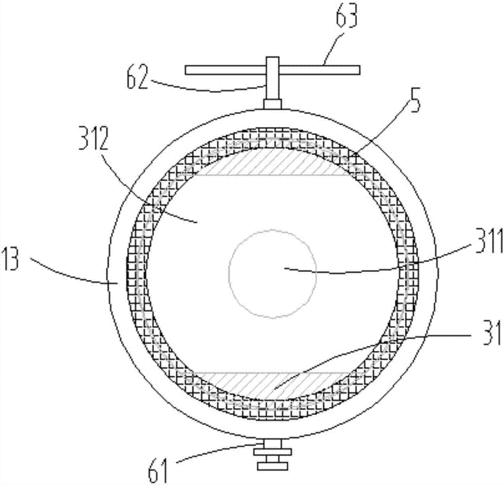
[0025] like Figure 1 to Figure 6 , the present invention discloses a tunnel assembly for wind power generator testing, including a first air duct 11, a second air duct 12, a third air duct 13, a first support frame 14, a fixed frame 15, and a third support frame 16 , blast mounting frame 21, motor 22, fan 23, wind speed regulating ball 31 and generator 4, the first air duct 11 and the third air duct 13 are fixedly connected with the two ends of the second air duct 12 respectively, the first air duct 11 and the third air duct 13 are respectively supported on the first supporting frame 14 and the third supporting frame 16, and the second air duct 12 is fixedly connected with the fixing frame 15. The blast mounting frame 21 is fixed in the inner cavity of the second air duct 12, the motor 22 is fixed on the blast mounting frame 21, and the output shaft of the motor 22 i...


PUM


Abstract

The invention discloses a tunnel assembly for wind driven generator testing. A first air duct and a third air duct are fixedly connected with the two ends of a second air duct correspondingly, and aresupported to a first supporting frame and a third supporting frame correspondingly; the second air duct is fixedly connected with a fixed frame; an air blowing installing frame is fixed in an inner cavity of the second air duct; a motor is fixed to the air blowing installing frame; an output shaft of the motor is fixedly connected with a fan; a wind speed adjusting ball is rotationally connectedinto an inner cavity of the third air duct; and a power generator is arranged on one side of the third air duct. By means of the tunnel assembly for wind driven generator testing, the flow speed of wind can be adjusted, the using condition of the power generator under different wind speeds is tested, the air blowing installing frame can effectively relieve vibration generated during operation of the motor, it is avoided that the vibration of the motor is directly transmitted to the second air duct, and therefore the abrasion disjoin phenomenon, caused by the vibration, of the joint of the second air duct and the first air duct and the joint of the second air duct and the third air duct is avoided, and the service life of a tunnel is prolonged.

Description

Technical field: [0001] The invention relates to a tunnel assembly for testing a wind power generator. Background technique: [0002] Most of the existing test tunnels used for testing generators have an integral structure. The test tunnels are long and occupy a large space, and the existing wind turbine test tunnels cannot adjust the size of the tunnel air outlet. If you want to change the wind The flow rate can only be achieved by changing the power of the blower. Using a high-power blower consumes a lot of power, and when replacing a different blower, the tunnel needs to be disassembled, which is very cumbersome to use. In addition, when the fan in the existing test tunnel is working, the vibration generated by the fan is directly transmitted to the tunnel. If things go on like this, it will cause wear at the junction of the tunnel, and then damage the tunnel. Invention content: [0003] The present invention provides a tunnel assembly for wind power generator testing ...

Claims


Application Information

Patent Timeline
Patent Type & Authority Applications(China)
IPC IPC(8): F03D17/00F04D25/08F04D27/00F04D29/00
CPCF03D17/00F04D25/08F04D27/003F04D29/002
Inventor 廖恩荣薛文彦陈荷雅
Owner NANJING HIGH DRIVE ELECTROMECHANICAL AUTOMATION EQUIP CO LTD
Learn More