Detection module, display device and electronic equipment

A display device and detection module technology, applied in the field of fingerprint identification, can solve the problems of inability to analyze fingerprint images, complex structure of the detection module, and low integration, and achieve the effect of high resolution, simple structure, and high integration

Active Publication Date: 2018-04-24
成都大超科技有限公司
View PDF9 Cites 5 Cited by
  • Summary
  • Abstract
  • Description
  • Claims
  • Application Information

AI Technical Summary

Problems solved by technology

The current mainstream fingerprint recognition technologies include optical fingerprint recognition, capacitive fingerprint recognition and ultrasonic fingerprint recognition, but they also have their own shortcomings, such as optical fingerprint recognition and capacitive fingerprint recognition. Unable to

Method used


Image

  • Detection module, display device and electronic equipment
  • Detection module, display device and electronic equipment
  • Detection module, display device and electronic equipment

Examples


no. 1 example

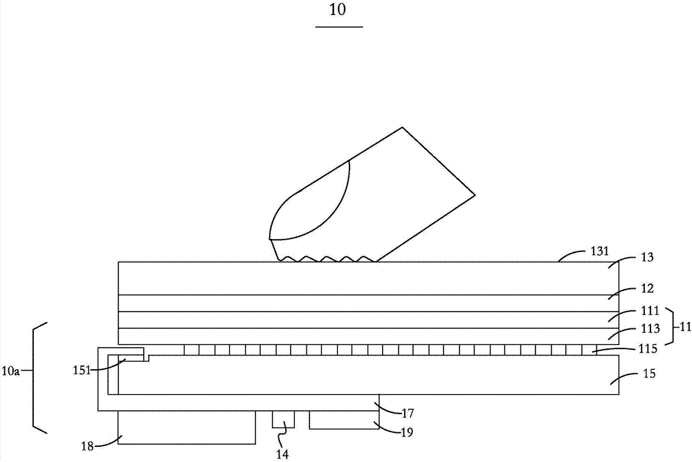
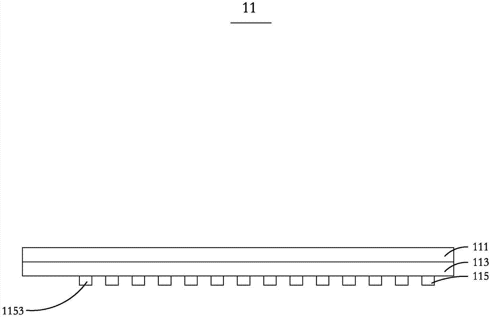
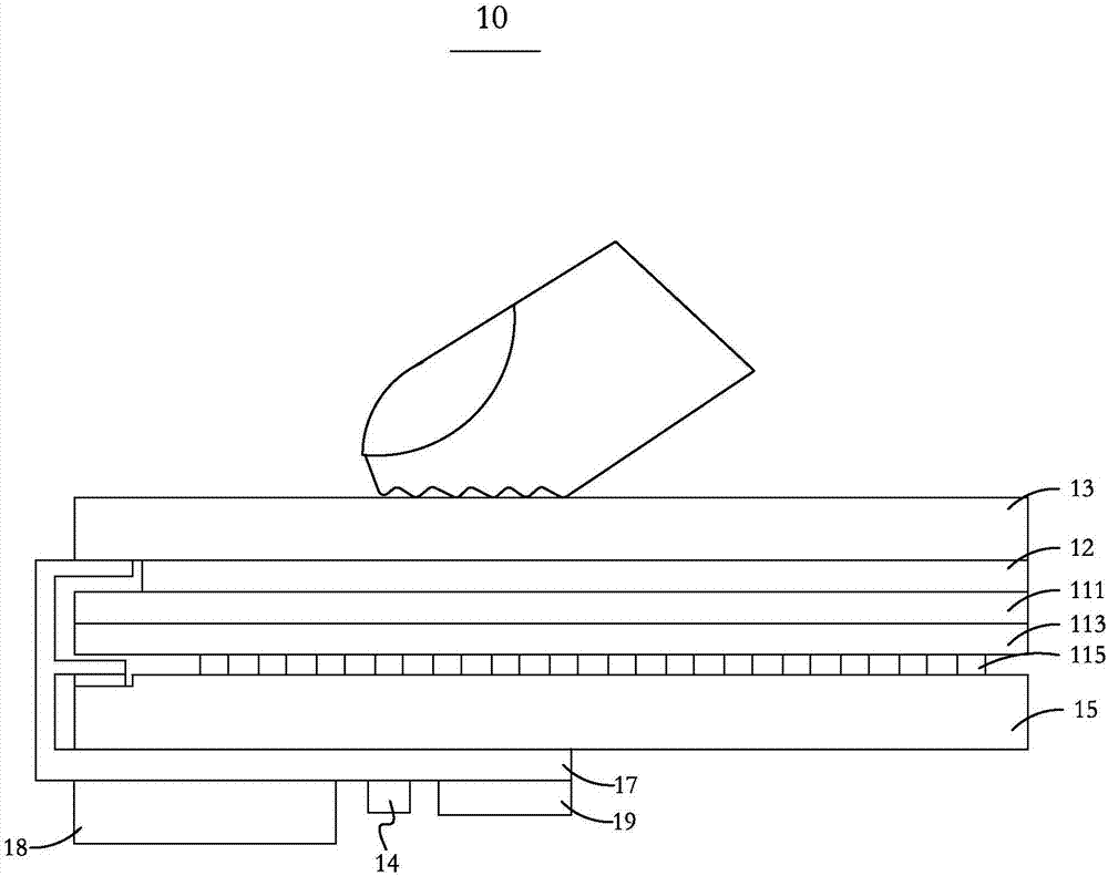
[0028] Please refer to figure 1 , the first embodiment of the present invention provides a display device 10, the display device 10 includes a detection module 10a, an adhesive layer 12 and a display module 13, one of the surfaces of the display module 13 is for the user to perform The operating touch surface 131 is provided with an adhesive layer 12 on the other surface opposite to the touch surface 131, and the adhesive layer 12 is bonded to the detection module 10a to enhance the connection strength between the detection module 10a and the display module 13. The size of the detection module 10a is equivalent to that of the display module 13, and the detection module 10a can not only perform fingerprint identification, but also can perform full-screen touch and pressure detection. The display module 13 may be some existing display modules in the market including basic structures such as display layer and cover glass, but preferably a display module including OLED (Organic Li...

no. 2 example

[0045] Please refer to Figure 5, the second embodiment of the present invention also provides another structure of the display device 20, the display device 20 includes a laminated cover plate 21, a first piezoelectric module 20a, a second piezoelectric module 21a, a display A module 22 , an adhesive layer 23 , a non-conductive substrate 25 and a circuit board 27 . One of the surfaces of the cover plate 21 is a touch surface 2111 for the user to operate, and the other surface opposite to the touch surface 2111 is provided with a first piezoelectric module 20a. The first piezoelectric module 20a and the second piezoelectric module 21a are arranged on two opposite surfaces of the display module 22, and the adhesive layer 23 is arranged on the surface of the display module 22 away from the cover plate 21 And it is located between the second piezoelectric module 21 a and the display module 22 . The non-conductive substrate 25 is disposed on the surface of the second piezoelectr...


PUM

PropertyMeasurementUnit
Thicknessaaaaaaaaaa

Abstract

The invention relates to the technical field of fingerprint recognition, and particularly to a detection module, a display device and electronic equipment. The detection module of the invention is used to be disposed on an opposite side of one side which is of a display module and is used for display, and realizes at least one function in fingerprint recognition, pressure sensing and touch recognition. In a direction from a place near the display module to a place away from the display module, the detection module includes an upper electrode layer, a piezoelectric layer, a lower electrode layer, a non-conductive substrate and a circuit board which are sequentially disposed in a laminated manner. The circuit board is electrically connected with the upper electrode layer and the lower electrode layer respectively. The size of the detection module is equivalent to the size of the display module. The detection module, the display device and the electronic equipment of the invention have the advantages of simple structures and high reliability, and more accord with trends of lightening and thinning and high integration degrees of electronic equipment.

Description

【Technical field】 [0001] The invention relates to the technical field of fingerprint identification, in particular to a detection module, a display device and electronic equipment. 【Background technique】 [0002] At present, fingerprint recognition technology has been widely used in many fields such as mobile terminals, smart homes, and crime fighting. It brings a lot of convenience and safety to people's life. The current mainstream fingerprint recognition technologies include optical fingerprint recognition, capacitive fingerprint recognition and ultrasonic fingerprint recognition, but they also have their own shortcomings, such as optical fingerprint recognition and capacitive fingerprint recognition. Fingerprint images cannot be resolved; and ultrasonic fingerprint recognition does not have such high requirements for the application environment, so ultrasonic fingerprint recognition is widely used. [0003] However, the structures of the existing detection modules are ...

Claims


Application Information

Patent Timeline
IPC IPC(8): G06K9/00
CPCG06V40/1306
Inventor 吴露向勇王开安高奇文
Owner 成都大超科技有限公司
Why Eureka
Try Eureka