
Pressing block trigger device and epoxy resin vacuum low pressure packaging process method

A trigger device, epoxy resin technology, applied in electrical components, electric solid state devices, semiconductor/solid state device manufacturing, etc., can solve the problems of affecting product appearance, high operating temperature, large solder stress, etc., and achieve a simple and reliable control method. Low operating temperature and small device damage

Pending Publication Date: 2018-04-24
NORTH ELECTRON RES INST ANHUI CO LTD
View PDF0 Cites 1 Cited by
  • Summary
  • Abstract
  • Description
  • Claims
  • Application Information

AI Technical Summary

Problems solved by technology

[0004] Epoxy resin bonding: The epoxy resin material has high fluidity, and it will spread and flow after the cover plate is placed, which will cause the failure of the internal components of the cavity and affect the appearance of the product. When the internal gas expands during heating and curing, air holes will be generated at the bonding interface and thus airtight failure
The traditional epoxy bonding method cannot achieve the internal vacuum / low pressure state, and some devices that require this cannot work effectively
[0005] Solder welding: high cost, high solder stress, incapable of encapsulating large-size housings, high operating temperature, and some temperature-sensitive devices cannot work effectively

Method used


Image

  • Pressing block trigger device and epoxy resin vacuum low pressure packaging process method
  • Pressing block trigger device and epoxy resin vacuum low pressure packaging process method
  • Pressing block trigger device and epoxy resin vacuum low pressure packaging process method

Examples


Embodiment Construction

[0030] The present invention will be further described below in conjunction with the accompanying drawings. The following examples are only used to illustrate the technical solution of the present invention more clearly, but not to limit the protection scope of the present invention.

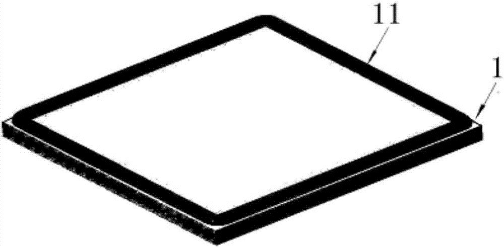
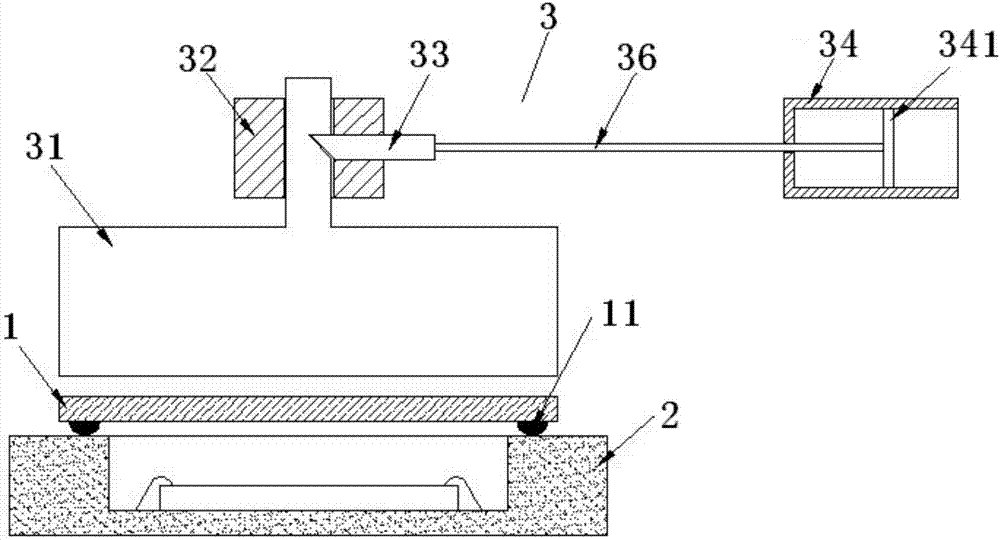
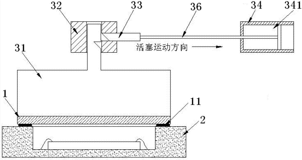
[0031] Such as figure 1 - image 3 As shown, the present invention uses pre-cured epoxy resin to realize the packaging of the cover plate 1 and the housing 2, covers the cover plate 1 pre-coated and cured epoxy resin 11 on the housing 2, and coats the epoxy resin 11 The face faces the housing 2 and fits with the housing. Place the casing 2 of the upper cover and the briquetting trigger device 3 in a vacuum oven. The oven is heated up. After reaching a certain temperature, the oven starts to vacuumize and triggers the briquetting to drop onto the cover 1, and then raises the temperature to the curing temperature and completes the curing.

[0032] Epoxy resin coating steps: choose pre-cured epo...


PUM


Abstract

The invention discloses a pressing block trigger device and an epoxy resin vacuum low pressure packaging process method. The device comprises a pressing block, a movable pin and a cylinder. The upperpart of the pressing block has a slide rod, and a front end of the movable pin can be embedded into a dovetail groove in a side of the slide rod. An end of the movable pin is connected to a piston inthe cylinder through a connecting rod, and the moving pin is driven by the movement of the piston to be embedded into the slide rod or withdrawn from the sliding rod. A pre-cured epoxy resin is used as a bonding material, the operation is more convenient than that of a traditional epoxy resin, the cost is lower than that of a soldering mode, and the operating temperature is low and has small damage to the device. A vacuum oven is used to cure epoxy resin, a vacuum / low pressure state in a sealed cavity is ensured, and the formation of sealed interface pores due to internal expansion during curing is avoided. An epoxy resin curing process is designed, vacuumizing is carried out in a preheating stage, the pressing block trigger device is used to control the pressing block to press a cover plate in falling, the discharge of gas inside the cavity is ensured, and the pre-cured epoxy resin can effectively bond.

Description

technical field [0001] The invention relates to an epoxy resin vacuum low-pressure packaging process method, which belongs to the technical field of ceramic shell packaging. Background technique [0002] Traditional ceramic shell packages generally adopt the method of epoxy resin bonding or soldering. Epoxy resin bonding is to pre-coat insulating epoxy resin on the bonding area, place the cover plate on the coated epoxy resin and fix it by clamping, and combine the shell and the cover plate together by heating and curing. Solder soldering is to apply solder paste or place pre-cut soldering sheets on the soldering area in advance, then place the cover plate on the solder paste / solder sheet and fix it, and melt the solder through high temperature, so that the cover plate and the shell are combined. The commonly used solder is gold tin solder. [0003] shortcoming: [0004] Epoxy resin bonding: The epoxy resin material has high fluidity, and it will spread and flow after the...

Claims


Application Information

Patent Timeline
IPC IPC(8): H01L21/67H01L21/56
CPCH01L21/56H01L21/67126H01L2224/48091H01L2924/16195H01L2924/00014
Inventor 李杰金龙宋哲宇
Owner NORTH ELECTRON RES INST ANHUI CO LTD
Learn More