
Automatic assembling machine of double-row eight-pin connector

A technology of automation group and connector, applied in the direction of assembly/disassembly of contacts, can solve the problems of unstable product quality, low product qualification rate, low detection efficiency, etc., to improve product assembly quality, high degree of automation, reduce The effect of labor

Inactive Publication Date: 2018-04-24
DONGGUAN UNIV OF TECH
View PDF0 Cites 9 Cited by
  • Summary
  • Abstract
  • Description
  • Claims
  • Application Information

AI Technical Summary

Problems solved by technology

[0002] There is a double-row eight-pin connector such as Figure 18 As shown, it includes a base 24, a first row of shrapnel 78 and a second row of shrapnel 77, and the contact ends of the two rows of shrapnel are respectively inserted into the inside of the base 24 from corresponding sockets provided at the bottom of the base 24. The double-row eight-pin connector also includes eight PIN needles 69 correspondingly connected to the two rows of shrapnel. The lower part of the PIN needle 69 is inserted into the inside of the base 24, and the upper part of the PIN needle 69 is bent twice to connect with the base. 24 at an angle of 30° to 40°, the base 24 is provided with a plastic part 40 below the bend of the PIN needle 69, however, in the prior art, on the one hand, this type of connector is manually or multiple Each piece of equipment separately assembles the components of the connector pin seat together, which has problems such as low assembly efficiency, unstable product quality, and low product qualification rate. On the other hand, the assembled connector is usually manually tested step by step. Sex, low detection efficiency

Method used


Image

  • Automatic assembling machine of double-row eight-pin connector
  • Automatic assembling machine of double-row eight-pin connector
  • Automatic assembling machine of double-row eight-pin connector

Examples


Embodiment Construction

[0041] In order to enable those skilled in the art to better understand the technical solution of the present invention, the present invention will be described in detail below in conjunction with the accompanying drawings. The description in this part is only exemplary and explanatory, and should not have any limiting effect on the protection scope of the present invention. .

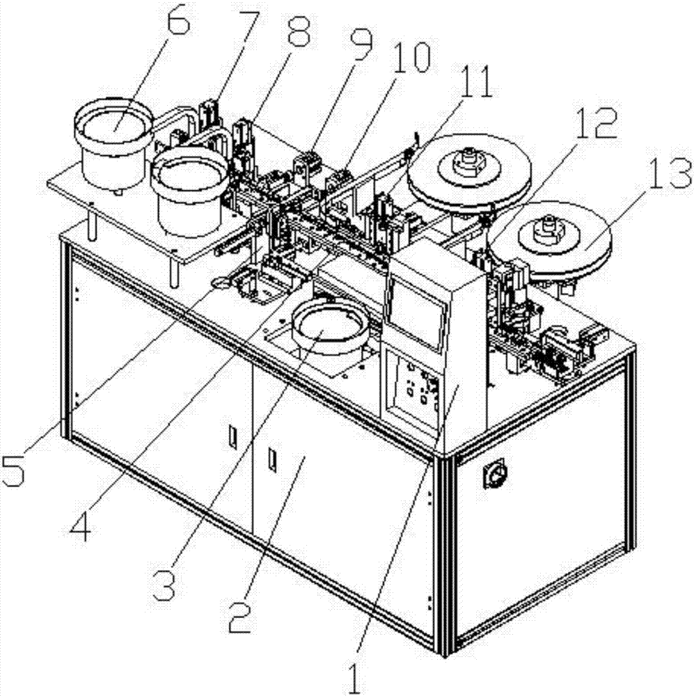
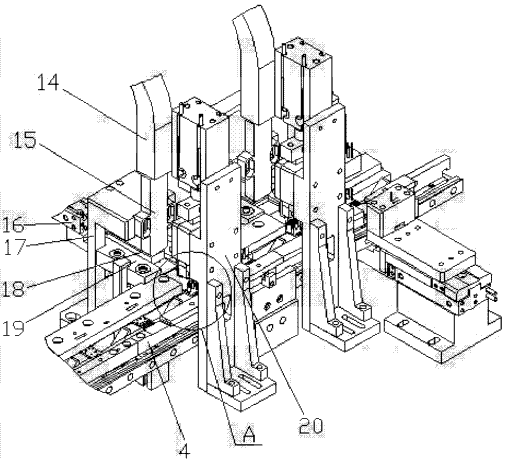
[0042] like Figure 1-Figure 18 As shown, the structure of the present invention is: an automatic assembly machine for a double-row eight-pin connector, which includes a frame 2, a control box 1 and a feeding track 4 arranged on the frame 1, above the feeding track 4 Along the conveying direction, a first pin insertion device 12, a second pin insertion device 11, a plastic parts feeding device 5, a first bending device 10, a second bending device 9, a first blade insertion device 8, a second The insertion device 7 and the detection device, the first pin insertion device 12 and the second pin insertion...


PUM


Abstract

The invention relates to an automatic assembly machine for a double-row eight-pin connector, which includes a frame, a control box and a feeding track arranged on the frame, above the feeding track along the conveying direction, a first pin insertion device, a second Pin insertion device, plastic parts feeding device, first bending device, second bending device, first blade insertion device, second blade insertion device and detection device, the first pin insertion device and the second pin insertion device are connected There is a PIN needle feeding plate, the plastic parts feeding device is connected to the plastic parts vibrating plate, the first inserting device and the second inserting device are connected to the shrapnel vibrating plate, and the entrance end of the feeding track is equipped with a CCD detection head and a tail end. Equipped with a detection device; it can automatically assemble the parts of the connector into a double-row eight-pin connector, which has a high degree of automation and assembly efficiency, reduces labor, stable product quality, and can automatically detect the conduction performance of the product at the same time , can effectively improve the product qualification rate.

Description

technical field [0001] The invention relates to connector assembly equipment, in particular to an automatic assembly machine for a double-row eight-pin connector. Background technique [0002] There is a double-row eight-pin connector such as Figure 18 As shown, it includes a base 24, a first row of shrapnel 78 and a second row of shrapnel 77, and the contact ends of the two rows of shrapnel are respectively inserted into the inside of the base 24 from corresponding sockets provided at the bottom of the base 24. The double-row eight-pin connector also includes eight PIN needles 69 correspondingly connected to the two rows of shrapnel. The lower part of the PIN needle 69 is inserted into the inside of the base 24, and the upper part of the PIN needle 69 is bent twice to connect with the base. 24 at an angle of 30° to 40°, the base 24 is provided with a plastic part 40 below the bend of the PIN needle 69, however, in the prior art, on the one hand, this type of connector is m...

Claims


Application Information

Patent Timeline
IPC IPC(8): H01R43/20
CPCH01R43/20
Inventor 廖梓龙邓君
Owner DONGGUAN UNIV OF TECH
Learn More