
Automatic assembling machine for adjusting studs

A technology for adjusting studs and assembling machines. It is used in manipulators, program-controlled manipulators, and metal processing. It can solve the problems of polluted product surface quality, bumped operator's fingers, and improper assembly. High-level, easy-to-replace effect

Inactive Publication Date: 2018-04-27
中山市小榄企业服务有限公司
View PDF4 Cites 4 Cited by
  • Summary
  • Abstract
  • Description
  • Claims
  • Application Information

AI Technical Summary

Problems solved by technology

[0002]The adjusting stud is composed of a screw and a nut. During production, the nut needs to be assembled on the screw. In the process of mechanical assembly, a large number of screws and nuts need to be assembled In the past, the assembly was done manually or with manual hand-held automatic tools. Due to the manual operation, the production efficiency was low and the labor intensity was high. During the distribution and assembly process of the screw and nut, surface bumps were likely to occur and the surface quality of the product would be polluted. , assembly is not in place and the phenomenon of bruising the operator's fingers
With the rapid development of the economy, the demand for screws and nuts is increasing. At the same time, higher requirements are put forward for the production efficiency, quality and cost of screw and nut assembly. The existing screw and nut assembly technology cannot meet the requirements. these requirements

Method used


Image

  • Automatic assembling machine for adjusting studs
  • Automatic assembling machine for adjusting studs
  • Automatic assembling machine for adjusting studs

Examples


Embodiment Construction

[0019] The present invention will be further described below in conjunction with the accompanying drawings, but the protection scope of the present invention is not limited to the following description.

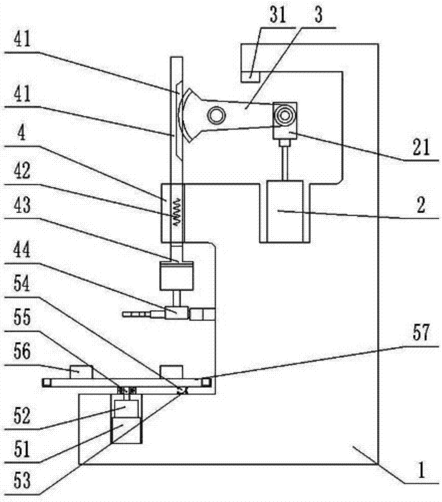
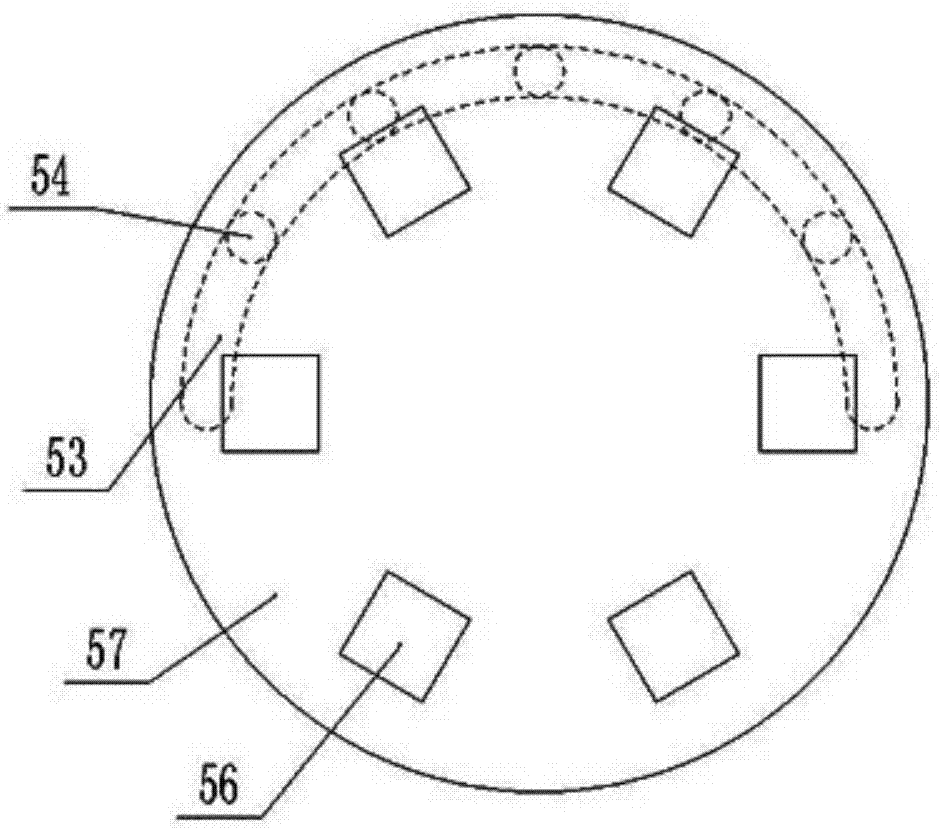
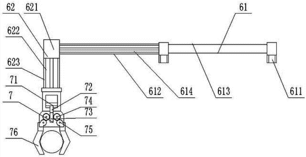
[0020] Such as Figure 1-3 As shown, an automatic assembly machine for adjusting studs includes a frame 1, a transition rod 41, a drive assembly 5 and a feeding device 6, the rear of the frame 1 is provided with a cylinder 2, and the rear of the frame 1 is provided with a cylinder for installation Seat, cylinder 2 is fixedly installed in the cylinder mounting seat,

[0021] The output shaft of the cylinder 2 is driven to connect the drive push rod 21, and the drive push rod 21 is rotatably connected to the sector gear 3, and the sector gear 3 is arranged on the frame 1 through shaft rotation; the transition rod 41 is provided with a rack 411, and the sector gear 3 Mesh and cooperate with the rack 411; in the working state of the present invention, the cylinder 2 is connected...


PUM


Abstract

The invention relates to an automatic assembling machine for adjusting studs. The automatic assembling machine comprises a rack, a transition rod, a driving assembly and a taking and sending device, wherein an air cylinder is arranged behind the rack, an air cylinder installation seat is arranged behind the rack, the air cylinder is fixedly installed in the air cylinder installation seat, an output shaft of the air cylinder is in driving connection with a driving push rod, the driving push rod is rotatably connected with a sector gear, and the sector gear is rotatably arranged on the rack by virtue of a shaft; a rack is arranged on the transition rod, and the sector gear is engaged with the rack; and a tightening motor is fixedly installed at the bottom of the transition rod. When the automatic assembling machine is operated, after a previous group of adjusting studs are assembled, a bedplate is driven to rotate at a certain angle by a servo motor, so that the next group of nuts are sent to a station, and the previous group of adjusting studs exit so as to be taken by operating personnel; a speed reducer is combined, so that a large output torque can be generated, the bearing capacity is high, the control accuracy of the rotating angle of the bedplate is increased, and the positioning accuracy of the adjusting studs at the station is guaranteed.

Description

technical field [0001] The invention relates to an automatic assembly machine, in particular to an automatic assembly machine for adjusting studs. Background technique [0002] The adjusting stud is composed of a screw and a nut. During production, the nut needs to be assembled on the screw. In the process of mechanical assembly, a large number of screws and nuts need to be assembled. In the past, the assembly was carried out manually or manually with automatic tools. Assembling, due to manual operation, its production efficiency is low and labor intensity is high. During the distribution and assembly process of screws and nuts, it is also prone to surface bumps, pollution of product surface quality, improper assembly and bruising of operators' fingers. With the rapid development of the economy, the demand for screws and nuts is increasing. At the same time, higher requirements are put forward for the production efficiency, quality and cost of screw and nut assembly. The exi...

Claims


Application Information

Patent Timeline
Patent Type & Authority Applications(China)
IPC IPC(8): B23P19/06B25J9/02B25J15/02
CPCB23P19/06B23P19/001B23P19/007B25J9/023B25J15/0213
Inventor 梅锦初
Owner 中山市小榄企业服务有限公司
Learn More