Material sorting device

A material distribution device and material storage device technology, which is applied in metal processing machinery parts, metal processing, measuring/indicating equipment, etc., can solve problems such as increasing the labor intensity of operators, liberating the hands of operators, and rejecting unqualified products. Achieve the effect of realizing mechanical automation production, automatic sorting of unqualified products, and reducing labor costs

Active Publication Date: 2018-04-27
宁波优耐特模具有限公司
6 Cites 2 Cited by

AI-Extracted Technical Summary

Problems solved by technology

[0002] In traditional mechanical processing and manufacturing, the material is transferred from the loading table to the unloading table through the conveyor belt of the feeding device. When the material is conveyed on the conveyor belt, the operator divides the material through manual intervention, which not only increases the operator's work Labor intensity, and the production efficiency is low, so there has been an automatic material distribution device. At present, more material distribution mechanisms are used to provide a fork frame on the support, and a container for...

Method used

Shrapnel is arranged in the concave cavity of second material distribution plate both sides by spring connection, and one end is positioned at waste material discharge hole, and one end extends to the second material distribution plate outside through cavity, and cooperates with touch counter, When the workpiece is discharged to the waste collection device through the waste discharge hole, it will touch one end of the shrapnel in the waste discharge hole. Since the ...

Abstract

The invention discloses a material sorting device which comprises a material sorting platform. The material sorting platform is provided with a material storing device with a material guide mouth, a material sorting device body which is supported by supporting seats is correspondingly arranged below the material guide mouth, and the rear of the material sorting device body is provided with an airsource processor. According to the material sorting device, the material sorting device body comprises structures of a material pressing mechanism, a material feeding plate, an infrared counter and the like, by means of the coordination of all the structures and the monitoring of a monitoring device, the effect of sorting unqualified products automatically is achieved; meanwhile, the waste productrate can be accurately calculated by counting inferior-quality products, thus the quality of equipment is further improved; and workpieces are sorted by mechanical means, the material sorting speed is increased, the efficiency of material sorting is improved, the factory is liberated from the heavy manual labor, the manpower cost is lowered, the machinery automation production of the factory is realized, and the error rate of manual sorting is directly avoided, and the product qualification rate is directly and effectively increased.

Application Domain

Measurement/indication equipmentsMetal working apparatus

Technology Topic

Waste productEngineering +1

Image

  • Material sorting device
  • Material sorting device
  • Material sorting device

Examples

  • Experimental program(1)

Example Embodiment

[0013] The present invention will be further described below in conjunction with the accompanying drawings and embodiments.
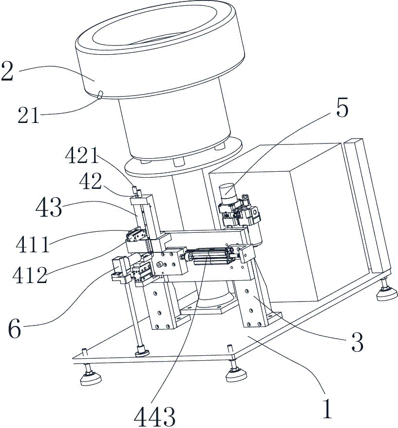
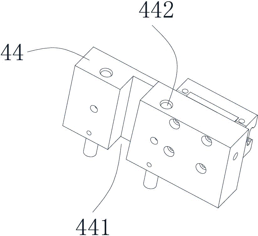
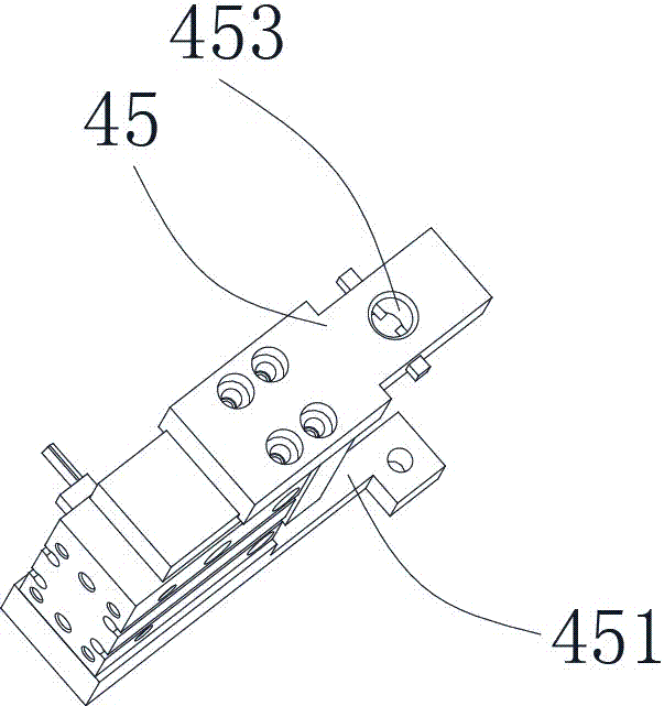
[0014] see Figure 1 to Figure 4 , a material distribution device, including a material distribution table 1, a material storage device 2 with a material guide port 21 is arranged on the material distribution table 1, and a distribution device supported by a support 3 is arranged below the material guide port 21. The material distribution device is provided with an air source processor 5 behind the material distribution device. The material distribution device includes a material pressing mechanism, a material feeding plate 43 equipped with an air pipe interface 42, an infrared counter 421 is arranged at the air pipe interface 42, and an infrared counter 421 is located at the air pipe interface 42. A first material distribution plate 44 and a second material distribution plate 45 are respectively arranged on the horizontal plane along the X and Y directions below the material plate 43, and the second material distribution plate 45 is arranged on the first material distribution plate through the second drive bracket 451 44, and the first distribution plate 44 is provided with an assembly groove 441 through which the second distribution plate 45 is embedded or withdrawn through the second drive mechanism 452, and two-way discharge holes 442 are provided on both sides of the assembly groove 441, located on the second The second material distribution plate 45 is provided with a waste material discharge hole 453, and a shrapnel 454 is symmetrically arranged in the waste material discharge hole, and the ends of the two symmetrically arranged shrapnel 454 cooperate with a touch counter 455, and the first material distribution plate 44 A first drive device 443 is provided on the side, and a monitoring device 6 connected to the drive mechanism is provided directly in front of the feeding plate 43 .
[0015] The air source processor 5 communicates with the air pipe interface, the monitoring device 6 is a camera, and the pressing mechanism includes a bracket 411 installed in the middle of the feeding plate and an X mounted on the bracket and perpendicular to the feeding plate. Binder cylinder 412 on the horizontal plane.
[0016] When the device is in use, after the workpiece conveyed by the material guide port enters the material feeding plate, an air source processor is installed behind the material distribution device to blow air to the air pipe interface, so as to assist the workpiece to pass through the material feeding plate smoothly and reach the material distribution plate At the same time, the infrared counter calculates the amount of the workpiece, and the monitoring device installed in front of the feeding plate monitors the status of the workpiece. If it meets the preset value, the cylinder of the first driving device is turned on. At this time, the first driving device pushes the first When the material distribution plate reaches the position of the material distribution plate, one hole in the two-way discharge hole corresponds to the material feeding plate, so that the workpiece enters the next process through the material feeding hole. If it does not meet the preset value, the second driving mechanism 452 Embed the second material distribution plate 45 into the assembly groove 441, make the waste material discharge hole correspond to the material feeding plate, and make the workpiece discharge into the waste material collection device through the waste material discharge hole. At the same time, during the material distribution process, the two-way discharge hole It can carry out two-way distribution of workpieces at the same time, and can supply workpieces to the next process in two directions at the same time, effectively improving the efficiency of the next process.
[0017] The shrapnel is arranged in the concave cavity on both sides of the second material distribution plate through spring connection, one end is located in the waste discharge hole, and the other end extends through the concave cavity to the outside of the second material distribution plate, and cooperates with the touch counter, and the workpiece passes through this When the waste material discharge hole is discharged to the waste material collection device, it will touch one end of the shrapnel in the waste material discharge hole. Since the shrapnel is fixed on the spring and one end is under pressure, the other end will be bounced out and touched. Touch the counter, every time a workpiece passes, the other end of the shrapnel will touch the counter once. By reading the data of the touch counter, it can not only achieve the effect of automatic sorting of unqualified products, but also accurately calculate the scrap rate, thereby further improving The quality of the equipment.
[0018] The scope of protection of the present invention includes but is not limited to the above embodiments. The scope of protection of the present invention is based on the claims. Any replacement, deformation, and improvement that are easily conceived by those skilled in the art for this technology fall within the scope of the present invention. protected range.

PUM

no PUM

Description & Claims & Application Information

We can also present the details of the Description, Claims and Application information to help users get a comprehensive understanding of the technical details of the patent, such as background art, summary of invention, brief description of drawings, description of embodiments, and other original content. On the other hand, users can also determine the specific scope of protection of the technology through the list of claims; as well as understand the changes in the life cycle of the technology with the presentation of the patent timeline. Login to view more.

Similar technology patents

Method for improving quality of strong aromatic dry distilled grain

ActiveCN101705167AIncrease the acidity in the cellarquality improvement
Owner:SICHUAN TUOPAI SHEDE WINE

Jujube tree grafting method

InactiveCN103070025Aprevent dehydrationquality improvement
Owner:XINJIANG ACADEMY OF AGRI & RECLAMATION SCI

High-yield pollution-free breeding method of freshwater fish

Owner:靖江市华信科技创业园有限公司

Friction-stir welding equipment

ActiveCN104985320Aquality improvementReduce torsional or impact forces
Owner:重庆派馨特机电有限公司

Classification and recommendation of technical efficacy words

Why Eureka
Try Eureka