
High-flow hydraulic ceramic plunger pump

A ceramic plunger, high flow technology, used in piston pumps, pumps, components of pumping devices for elastic fluids, etc., can solve the problem of affecting the service life of seals, cannot be effectively and timely It can meet the needs and other problems well, and achieve the effect of guaranteeing the service life.

Pending Publication Date: 2018-04-27
ZHEJIANG SINOU ENVIRONMENTAL PROTECTION EQUIP CO LTD
View PDF0 Cites 2 Cited by
  • Summary
  • Abstract
  • Description
  • Claims
  • Application Information

AI Technical Summary

Problems solved by technology

[0002] The flow rate of the existing plunger pump is small, which cannot meet the demand well
During the operation of the existing plunger pump, because the sludge contains air, it will be separated from the sludge under pressure and remain in the pump cavity and cannot be discharged. The friction between the air and the ceramic plunger will generate heat, which will affect Seal life
The existing plunger pumps are difficult to maintain, and cannot be dealt with effectively and in a timely manner when a failure occurs

Method used


Image

  • High-flow hydraulic ceramic plunger pump

Examples


Embodiment Construction

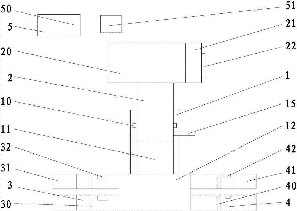
[0015] refer to figure 1 , a large-flow hydraulic ceramic plunger pump of the present invention, comprising a hydraulic device 20, a ceramic plunger 2, a pump body 1, a main chamber 12, a sealing ring 11, a feed pipe 3, a discharge pipe 4, and a control processing device 5 , the pump body 1 is provided with a mounting hole 10, a sealing ring 11 is provided in the mounting hole 10, the ceramic plunger 2 is mounted on the mounting hole 10, the ceramic plunger 2 is connected with the hydraulic device 20, and the hydraulic device 20 is connected with the control processing device 5, the pump body 1 is provided with a main chamber 12, the main chamber 12 communicates with the installation hole 10, and the pump body 1 is equipped with a number of feed pipes 3 and a number of discharge pipes The pipe 4, the feed pipe 3 and the discharge pipe 4 are all in communication with the main chamber 12, the feed pipe 3 is provided with a first one-way valve 30, and the discharge pipe 4 is prov...


PUM


Abstract

The invention discloses a high-flow hydraulic ceramic plunger pump. The high-flow hydraulic ceramic plunger pump comprises a hydraulic device, a ceramic plunger pump body, a pump body, a main containing cavity, a seal ring, a plurality of feed pipes, a plurality of discharge pipes and a control and processing device. The pump body is provided with a mounting hole. The seal ring is arranged in themounting hole. The ceramic plunger pump body is mounted on the mounting hole and is connected with the hydraulic device. The hydraulic device is connected with the control and processing device. The main containing cavity is formed in the pump body and communicates with the mounting hole. The plurality of feed pipes and the plurality of discharge pipes are mounted on the pump body and communicatewith the main containing cavity. A first one-way valve is arranged in each feed pipe. A second one-way valve is arranged in each discharge pipe. According to the high-flow hydraulic ceramic plunger pump, the plurality of feed pipes and the plurality of discharge pipes communicate with the main containing cavity so that the plunger pump can obtain high flow.

Description

【Technical field】 [0001] The invention relates to the technical field of environmental protection, in particular to the technical field of hydraulic ceramic plunger pumps. 【Background technique】 [0002] The flow rate of the existing plunger pump is relatively small, which cannot satisfy the demand well. During the operation of the existing plunger pump, because the sludge contains air, it will be separated from the sludge under pressure and remain in the pump cavity and cannot be discharged. The friction between the air and the ceramic plunger will generate heat, which will affect The service life of the seal. The existing plunger pumps are difficult to maintain, and cannot be dealt with effectively and in a timely manner when a failure occurs. 【Content of invention】 [0003] The purpose of the present invention is to solve the problems in the prior art, and propose a large-flow hydraulic ceramic plunger pump, which can make the plunger pump have a large flow rate, and ...

Claims


Application Information

Patent Timeline
IPC IPC(8): F04B9/10F04B49/00F04B53/00F04B53/06F04B53/16
CPCF04B9/10F04B49/00F04B53/00F04B53/06F04B53/16
Inventor 万安铭戴进明
Owner ZHEJIANG SINOU ENVIRONMENTAL PROTECTION EQUIP CO LTD
Learn More