Hydraulic floating caliper disc type brake device

A disc brake and floating caliper technology, applied in the direction of brake actuators, gear transmission mechanisms, axial brakes, etc., can solve the problems of difficulty in adapting to the use requirements, complex brake caliper structure, and large hydraulic pressure consumption, etc., to achieve Good practicability, simple structure, and the effect of improving the effect speed

Inactive Publication Date: 2018-04-27
宋建毅
View PDF0 Cites 13 Cited by
  • Summary
  • Abstract
  • Description
  • Claims
  • Application Information

AI Technical Summary

Problems solved by technology

[0004] Caliper disc brakes can be divided into fixed caliper disc type and floating caliper disc type according to the structure of the brake caliper. The brake caliper of the hydraulic floating caliper disc brake device is floating and can move axially relative to the brake disc. , because during the braking process, the oi

Method used


Image

  • Hydraulic floating caliper disc type brake device
  • Hydraulic floating caliper disc type brake device

Examples


Embodiment 1

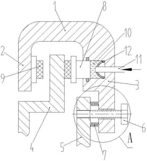
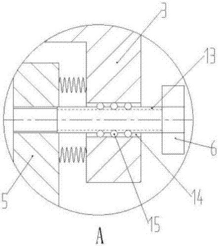
[0025] like figure 1 and figure 2 As shown, a hydraulic floating caliper disc brake device includes a brake caliper 1 and a brake disc 4. The brake caliper 1 is provided with a first brake arm 2 and a second brake arm 3. The boom 2 and the second brake arm 3 form a U-shaped structure with the brake caliper 1; the first brake arm 2 and the second brake arm 3 are respectively located on both sides of the brake disc 4, and the first brake arm 2 and the second brake arm 3 are provided with a friction plate 9 that can frictionally brake with the brake disc 4; the second brake arm 3 is provided with an oil chamber 10, and a piston is arranged in the oil chamber 10 8. A rubber air bag 12 is also provided on the wall of the oil chamber 10, and the rubber air bag 12 is filled with gas and is located on the moving axis of the piston 8; The axle 5 is connected so that the brake caliper 1 can slide on the guide rod 6 ; a reset mechanism is also provided between the guide rod 6 and the ...


PUM


Abstract

The invention discloses a hydraulic floating caliper disc brake device, which comprises a brake caliper and a brake disc, a first brake arm and a second brake arm are arranged on the brake caliper, the first brake arm and the second brake The boom and the brake caliper form a U-shaped structure; the first brake arm and the second brake arm are respectively located on both sides of the brake disc, and the first brake arm and the second brake arm are equipped with Friction plate for disc friction brake; the second brake arm is provided with an oil chamber, and a piston is arranged in the oil chamber; a rubber airbag is also arranged on the wall of the oil chamber, and the rubber airbag is filled with gas and located at the center of the piston. The moving axis is upward; the second brake arm is connected with the axle through the guide rod; there is also a reset mechanism between the guide rod and the second brake arm; through the structural improvement of the existing hydraulic floating caliper disc brake device, the It can have fast braking response, and can ensure that the braking device of the present invention has good braking efficiency, has simple structure, good performance, and is suitable for popularization and application.

Description

technical field [0001] The invention relates to the field of brakes, in particular to a hydraulic floating caliper disc brake device. Background technique [0002] A brake is a device that has the functions of slowing down, stopping or maintaining a stopped state of moving parts (or moving machinery). It is a mechanical part that stops or slows down moving parts in machinery, commonly known as brakes and brakes. The brake is mainly composed of frame, brake parts and operating device. Some brakes are also equipped with an automatic adjustment device for the clearance of the brake parts. In order to reduce the braking torque and structural size, the brakes are usually installed on the high-speed shaft of the equipment, but large equipment with higher safety requirements should be installed near the equipment. On the low-speed shaft of the working part. [0003] At present, friction brakes are mostly used in automobiles, which use the friction between the fixed element and th...

Claims


Application Information

Patent Timeline
IPC IPC(8): F16D55/226F16D65/00F16D65/14F16D121/02F16D121/04F16D123/00F16D125/14
CPCF16D55/226F16D65/0087F16D65/14F16D2055/0012F16D2055/0041F16D2121/02F16D2121/04F16D2123/00F16D2125/14
Inventor 宋建毅
Owner 宋建毅
Why Eureka
Try Eureka