
Heat exchange device and air conditioning device

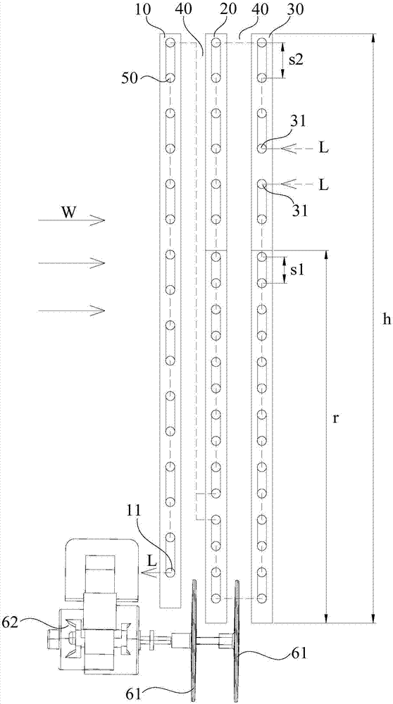
A technology for heat exchange devices and heat exchangers, which is applied in the field of heat exchange devices and air-conditioning equipment. It can solve the problems of large differences in refrigerant pressure and two-phase states, prone to abnormal noise, and suppression of heat transfer efficiency of heat exchangers. The pressure and the two-phase state are basically the same, the refrigerant pressure and the two-phase state are consistent, and the heat exchange efficiency is roughly balanced

Active Publication Date: 2018-04-27
GD MIDEA AIR-CONDITIONING EQUIP CO LTD +1
View PDF7 Cites 0 Cited by
  • Summary
  • Abstract
  • Description
  • Claims
  • Application Information

AI Technical Summary

Problems solved by technology

[0002] In existing air-conditioning equipment, the heat exchange efficiency of the heat exchanger is directly related to the energy efficiency ratio of the air conditioner, and for mobile air-conditioning equipment, the insufficient heat exchange efficiency of the condenser will directly lead to the reheating of the condenser. After the high-temperature hot air generated by heat exchange enters the volute of the outdoor side fan, it will cause overheating and deformation of the fan volute, the motor installation structure, etc., and make the whole machine fail to operate. The heat exchanger is cooled by water cooling to avoid the overheating problem. In the process of realizing the present invention, the inventor found that there are at least the following problems in the prior art: when the heat exchanger is assisted by water cooling, the cooling water coverage has uniformity. The limitation reduces the uniformity of the overall heat dissipation on the heat exchanger, and the pressure of the refrigerant and the two-phase state at different positions of the heat exchanger are greatly different, which is prone to abnormal noise, and it is also easy to make the heat transfer efficiency of each area of ​​the heat exchanger uneven, making the heat exchanger The overall heat exchange efficiency of the heater is suppressed, resulting in a decrease in the energy efficiency of the air conditioner

Method used


Image

  • Heat exchange device and air conditioning device

Examples


Embodiment Construction

[0035] In order to understand the above-mentioned purpose, features and advantages of the present invention more clearly, the present invention will be further described in detail below in conjunction with the accompanying drawings and specific embodiments. It should be noted that, in the case of no conflict, the embodiments of the present application and the features in the embodiments can be combined with each other.

[0036] In the following description, many specific details are set forth in order to fully understand the present invention. However, the present invention can also be implemented in other ways different from those described here. Therefore, the protection scope of the present invention is not limited by the specific details disclosed below. EXAMPLE LIMITATIONS.

[0037] Refer below figure 1 The heat exchange device according to some embodiments of the present invention is described.

[0038] Such as figure 1 As shown, the heat exchange device provided by t...


PUM


Abstract

The invention provides a heat exchange device and an air conditioning device. The heat exchange device comprises a water-cooling device; at least two sub -heat exchangers are arranged at intervals inthe wind direction, the water-cooling device is used for sending water to intervals, wherein for one sub-exchanger, located at the downstream of the wind direction, of any adjacent sub -heat exchangers, and an area of the influent location of adjacent intervals in the sub -heat exchanger is a water-cooling strengthening area; and each sub -heat exchanger comprises multiple refrigerant liquid pipes, and for the same sub -heat exchanger, the tube pitch of the refrigerant liquid pipes in the water-cooling strengthening area is less than the tube pitch of the refrigerant liquid pipes outside the water-cooling strengthening area. According to the heat exchange device, uniform heat exchange efficiency of each area of each sub -heat exchanger can be achieved, the problem of abnormal sound of therefrigerant liquid pipes is avoided, at the same time, the whole heat exchange efficiency of the heat exchange device can be integrally promoted, and the efficiency ratio of an air conditioning devicewhole machine which the heat exchange device is contained in is enhanced.

Description

technical field [0001] The present invention relates to the field of air conditioners, in particular to a heat exchange device and an air conditioner. Background technique [0002] In existing air-conditioning equipment, the heat exchange efficiency of the heat exchanger is directly related to the energy efficiency ratio of the air conditioner, and for mobile air-conditioning equipment, the insufficient heat exchange efficiency of the condenser will directly lead to the reheating of the condenser. After the high-temperature hot air generated by heat exchange enters the volute of the outdoor side fan, it will cause overheating and deformation of the fan volute, motor installation structure, etc., and make the whole machine fail to operate. The heat exchanger is cooled by water cooling to avoid the overheating problem. In the process of realizing the present invention, the inventor found that there are at least the following problems in the prior art: when the heat exchanger i...

Claims


Application Information

Patent Timeline
Patent Type & Authority Applications(China)
IPC IPC(8): F25B39/00F24F13/30F25D17/02F25D17/04
CPCF24F13/30F25B39/00F25D17/02F25D17/04
Inventor 梁凯刘从峰林军国
Owner GD MIDEA AIR-CONDITIONING EQUIP CO LTD
Learn More