Heat pump drying device and application method thereof

A technology of heat pump drying and drying method, which is applied in the direction of drying gas arrangement, heat pump, drying, etc., which can solve the problems of small application range of drying, easy damage of dried materials, incomplete evaporation, etc., and achieve expansion of application range and flexibility, Improvement of flexibility and reliability, and improvement of functional diversity

Active Publication Date: 2018-04-27
陈胜君
View PDF12 Cites 2 Cited by
  • Summary
  • Abstract
  • Description
  • Claims
  • Application Information

AI Technical Summary

Problems solved by technology

However, the existing drying devices and their drying methods usually have the following problems: they usually rely on heating equipment to heat the air to a high temperature and then dry the objects. Diversified drying methods, the dry matter is easy to be damaged and deteriorated, the scope of drying is very small, and usually a large amount of waste gas and waste heat need to be discharged, the energy consumption is large, the drying efficiency is low, and it is easy to pollute the environment, and the common heat pump drying system is harmful to drying The adaptability to process changes is small, and the compressor is prone to liquid hammer, which affects the reliability of the system
It can be seen from the technical mechanism of the above-mentioned patent that, in addition to dividing the drying process into two stages and setting different evaporation temperatures, the patented technology still basically follows the conventional high-temperature drying technology, which fails to solve the problem of conventional drying. The above-mentioned problems in the technology
Moreover, the auxiliary condenser described in this patent is connected to the back of the condenser. The refrigerant discharged from the compressor in the heat pump cycle first enters the condenser for cooling. In this state, the cooled liquid refrigerant enters the auxiliary condenser. Even if the auxiliary condenser is turned on, the heat dissipation capacity of the auxiliary condenser becomes very small, which has no effect on the working state of the heat pump system. In addition, there is no pre-cooler installed in this technology. If the working conditions of the heat pump system change greatly, the refrigerant flowing into the evaporator will also change greatly, which will easily cause the refrigerant to evaporate incompletely in the evaporator and cause The compressor is damaged by liquid return, so this patented technology does not have the ability to dry functional diversity

Method used


Image

  • Heat pump drying device and application method thereof
  • Heat pump drying device and application method thereof
  • Heat pump drying device and application method thereof

Examples


Embodiment Construction

[0030] The present invention will be further described in detail below in conjunction with examples, but the embodiments of the present invention are not limited thereto.

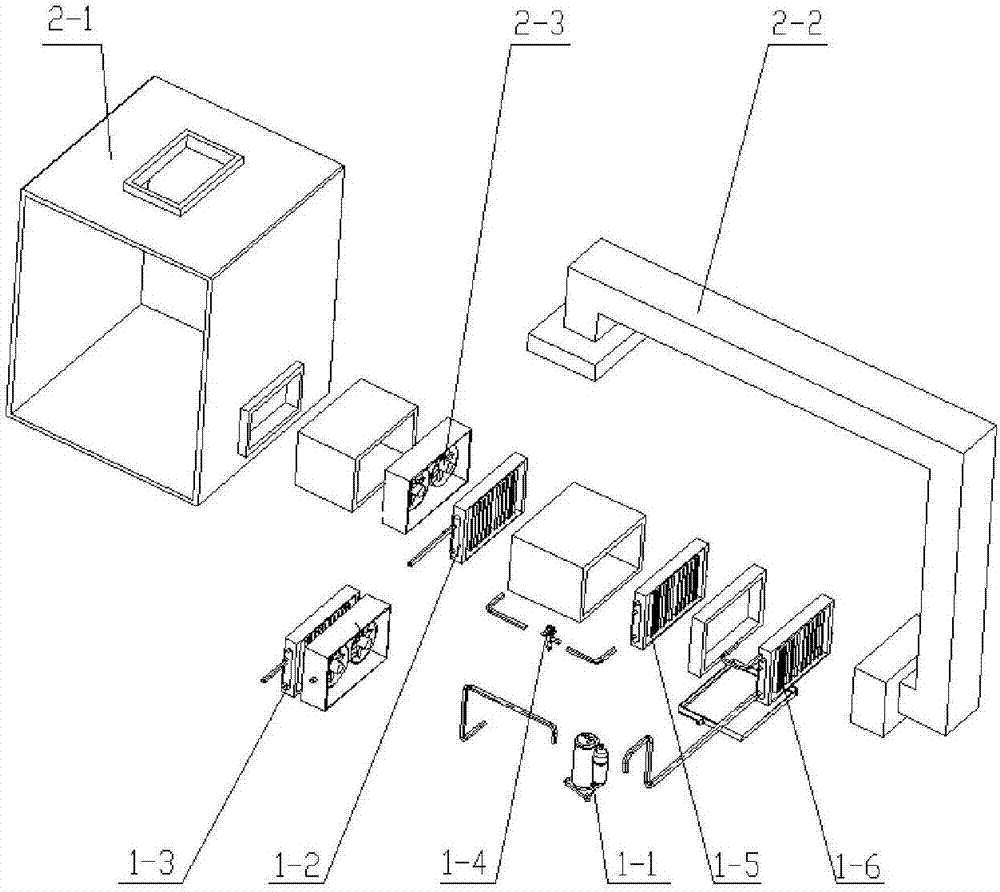
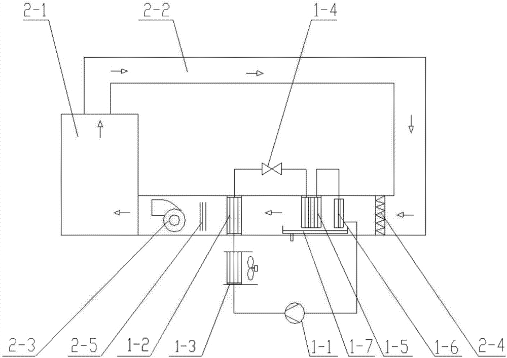
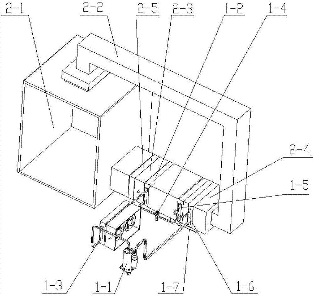
[0031] A heat pump drying device of the present invention can be found in the attached figure 1 - attached Figure 5 , consists of two parts, the heat pump circulation subsystem and the drying circulation subsystem. The heat pump circulation subsystem includes: a compressor (1-1), a heat regulating device (1-3), a condenser (1-2), a throttle (1-4), an evaporator (1-5) , Precooling heat exchanger (1-6). The drying cycle subsystem includes: a drying chamber (2-1), an air duct (2-2), and a drying fan (2-3).

[0032] In the heat pump cycle subsystem, the exhaust port of the compressor (1-1) is connected to the inlet of the heat regulating device (1-3) through the pipeline parts, and the outlet of the heat regulating device (1-3) is connected to the condenser ( 1-2) The inlet is connected, the outlet of the ...


PUM


Abstract

The invention discloses a heat pump drying device and an application method thereof. The heat pump drying device comprises a heat pump circulation subsystem and a drying circulation subsystem. A compressor, a heat adjustment device, a condenser, a throttling component, an evaporator and a precooling heat exchanger are connected through a pipeline, so that the heat pump circulation subsystem is formed. The drying circulation subsystem comprises a drying chamber, an air channel and a drying fan. The drying fan, the precooling heat exchanger, the evaporator and the condenser are mounted in the air channel, or air inlets of the drying fan, the precooling heat exchanger, the evaporator and the condenser and air outlets of the drying fan, the precooling heat exchanger, the evaporator and the condenser are connected with a front air channel body and a rear air channel body correspondingly. The drying chamber or the air channel body adjacent to the drying chamber is internally provided with atemperature sensor and a humidity sensor. By means of the heat pump drying device and the application method thereof, the problems that existing drying devices are small in function number, small in drying application scope, high in energy consumption, loss and emission and the like are solved; functional diversity and high efficiency of a drying system are achieved; the application scope is widened; damage of dried objects and emission of exhaust gas are reduced; and flexibility and reliability of the heat pump system are improved.

Description

technical field [0001] The invention relates to a drying device and a drying method, in particular to a heat pump drying device and a using method thereof. Background technique [0002] Common drying devices in the prior art are divided into electric heating drying devices and heat pump drying devices. Drying devices are often used in drying fields such as clothes, materials, chemicals, food or agricultural, forestry, animal husbandry and fishery products. However, the existing drying devices and their drying methods usually have the following problems: they usually rely on heating equipment to heat the air to a high temperature and then dry the objects. Diversified drying methods, the dry matter is easy to be damaged and deteriorated, the scope of drying is very small, and usually a large amount of waste gas and waste heat need to be discharged, the energy consumption is large, the drying efficiency is low, and it is easy to pollute the environment, and the common heat pump...

Claims


Application Information

Patent Timeline
Patent Type & Authority Applications(China)
IPC IPC(8): F26B21/00F26B21/10F25B30/06F25B41/00F25B41/40
CPCF25B30/02F25B30/06F25B41/00F26B21/002F26B21/10F26B23/10Y02P70/10
Inventor 陈胜君
Owner 陈胜君
Why Eureka
Try Eureka