
A high-temperature vacuum wind tunnel test chamber and diffuser integral structure with sliding thermal compensation function and sliding thermal compensation method

A high-temperature vacuum and wind tunnel test technology, applied in the field of wind tunnel, to achieve the effect of increasing the contact area, simplifying the structure design, and reducing the thermal stress

Active Publication Date: 2019-07-12
BEIJING AEROSPACE INST OF THE LONG MARCH VEHICLE +1
View PDF7 Cites 0 Cited by
  • Summary
  • Abstract
  • Description
  • Claims
  • Application Information

AI Technical Summary

Problems solved by technology

It solves the problem of thermal compensation of the diffuser in a high-temperature vacuum environment, with a simpler structure, strong adaptability to harsh high-temperature thermal environments, and no problem of thermal stress concentration

Method used


Image

  • A high-temperature vacuum wind tunnel test chamber and diffuser integral structure with sliding thermal compensation function and sliding thermal compensation method
  • A high-temperature vacuum wind tunnel test chamber and diffuser integral structure with sliding thermal compensation function and sliding thermal compensation method
  • A high-temperature vacuum wind tunnel test chamber and diffuser integral structure with sliding thermal compensation function and sliding thermal compensation method

Examples


Embodiment Construction

[0034] The present invention will be further described in detail below in conjunction with the accompanying drawings and specific embodiments.

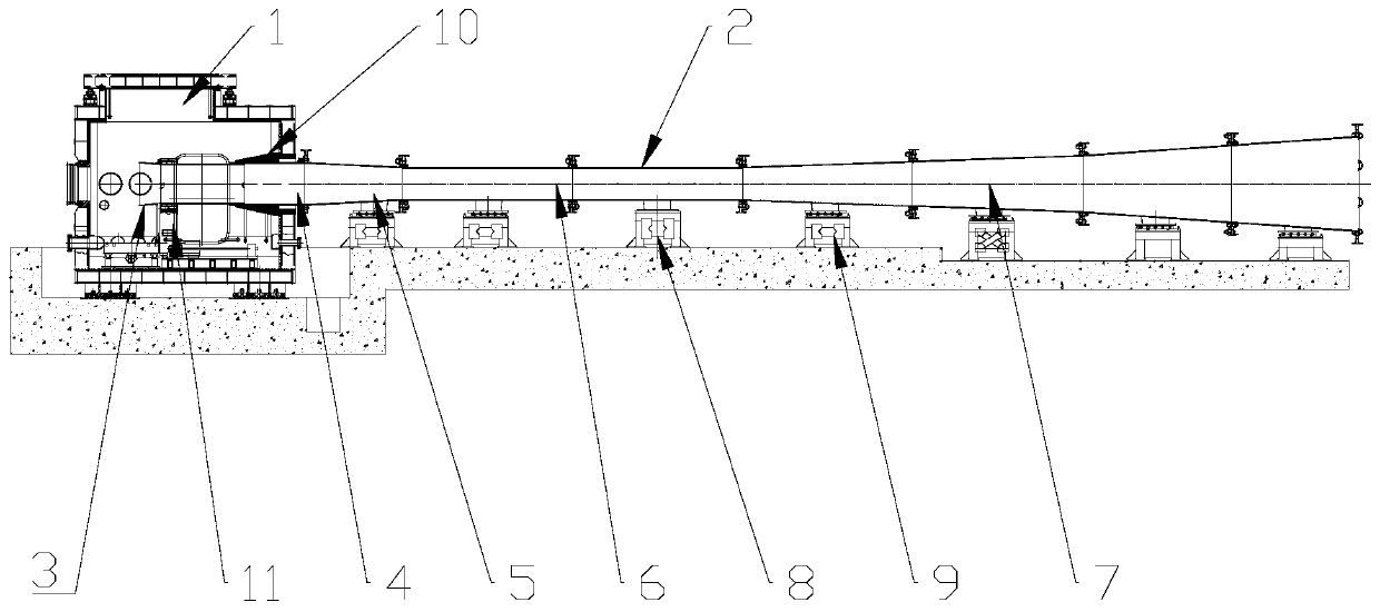
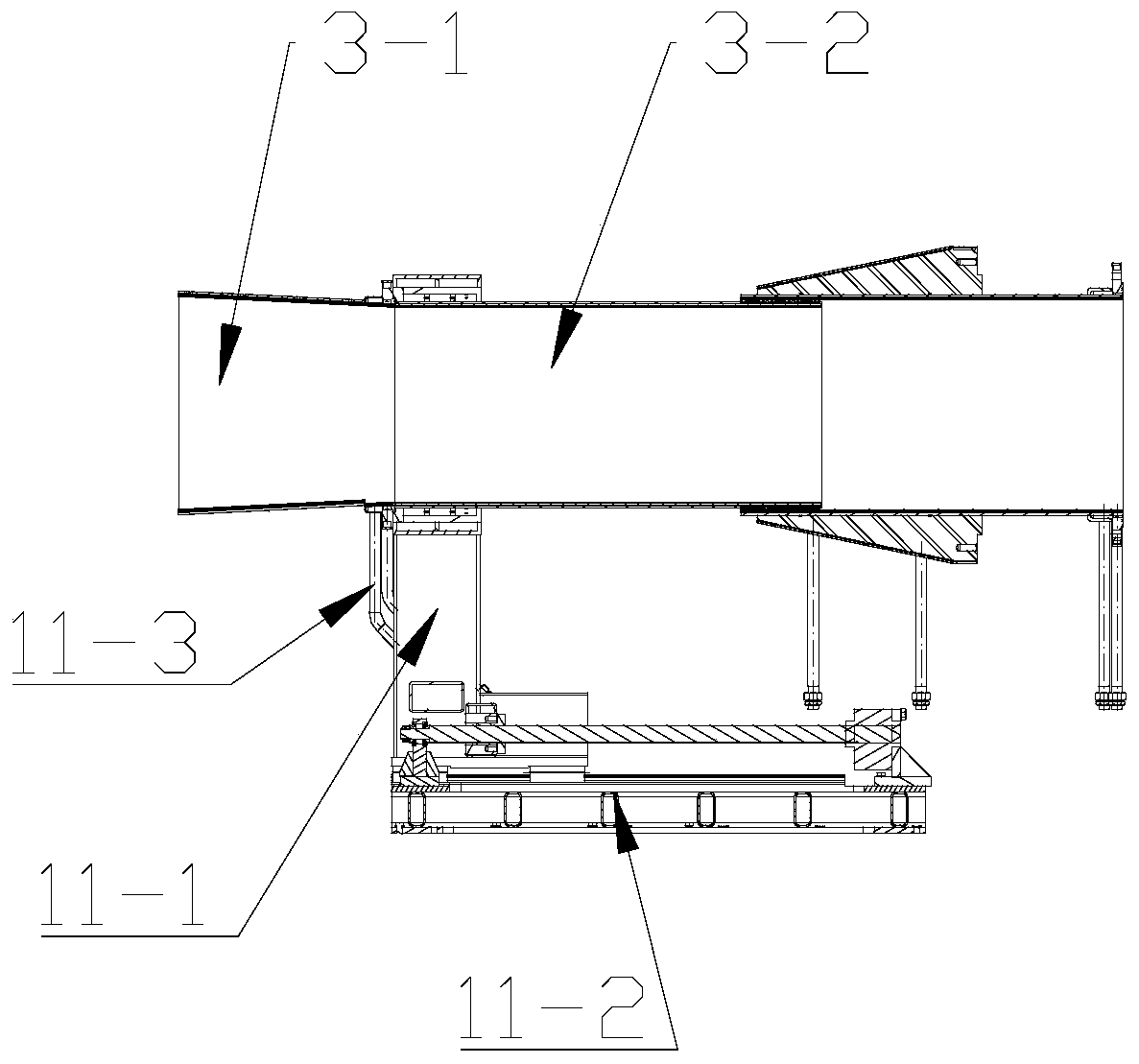
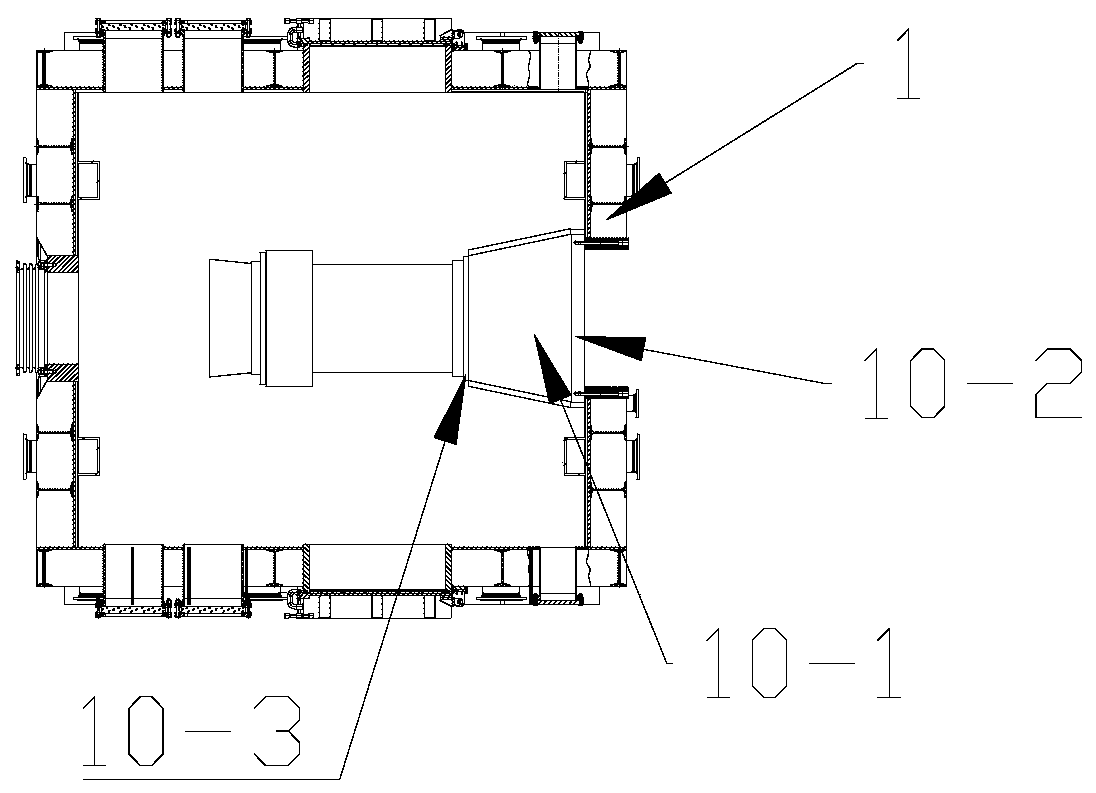
[0035] The present invention provides a high-temperature vacuum wind tunnel test chamber with a sliding thermal compensation function, an overall structure of a diffuser and a sliding thermal compensation method, which overcomes the deficiencies of the prior art, and provides a thermal compensation scheme for a high-temperature wind tunnel diffuser, Solve the problem of thermal compensation in the large gas flow wind tunnel test chamber in the harsh thermal environment of long time, high temperature and large heat flow. The structural design of fixed support in the middle of the diffuser and sliding at both ends is adopted to reasonably distribute the amount of thermal expansion. Depending on the thermal environment, different thermal compensation methods are used at different locations. Upstream: The contact area between the cabin a...


PUM


Abstract

The invention relates to a high temperature vacuum wind tunnel test cabin with the sliding thermal compensation function, a diffuser integral structure and a sliding thermal compensation method, solves disadvantages in the prior art, provides a thermal compensation scheme of a high temperature wind tunnel diffuser and solves a problem of thermal compensation difficulty of a large-scale gas flow wind tunnel test cabin under long-time, high temperature and large thermal flow bad thermal environments. A structure design of the diffuser of which the middle segment is fixed and supported and two ends are in a sliding mode is employed, and thermal expansion is reasonably distributed. According to the different thermal environments, different thermal compensation modes are employed at different positions. For the upstream, the contact area between a cabin body and the diffuser is enhanced through adding a conic sleeve, multi-channel sealing is employed to eliminate being-burnt and sealing failure risks, an upstream end of the diffuser, namely a collection port, is a free end, and sliding thermal compensation is realized; for the downstream, after a water spraying temperature reduction device is employed to reduce the gas temperature, an expansion knot thermal compensation method is employed, and sliding thermal compensation is realized.

Description

technical field [0001] The invention relates to a high-temperature vacuum wind tunnel test chamber with a sliding thermal compensation function, an overall structure of a diffuser and a sliding thermal compensation method, that is, a structure and a sliding thermal compensation method for a high-temperature vacuum wind tunnel with sliding thermal compensation, belonging to The field of wind tunnel technology. Background technique [0002] The high-temperature gas flow wind tunnel is an important ground test equipment for simulating the thermal performance of materials and aircraft in high-temperature airflow. The test cabin and diffuser are the main components of the wind tunnel. The pressure regulator is mainly used to increase the static pressure of the air flow to facilitate the discharge air flow. Compared with other wind tunnels, the high-temperature wind tunnel has the characteristics of large heat flow and long test time. In the gas flow wind tunnel, the thermal env...

Claims


Application Information

Patent Timeline
Patent Type & Authority Patents(China)
IPC IPC(8): G01M9/02
CPCG01M9/02
Inventor 曹知红田宁邹样辉齐斌赵玲岳晖张凯张利嵩那伟杨驰李彦良夏吝时姜一通李文浩肖泽娟张昕曹宇清鲁宇朱广生李建林孟刚周岩水涌涛张岩陈卫国黄凯
Owner BEIJING AEROSPACE INST OF THE LONG MARCH VEHICLE
Learn More