Quasi-static test device and method for base-free reinforced concrete column

A technology of reinforced concrete column and test device, which is applied to measurement devices, instruments, scientific instruments, etc., can solve the problems of large amount of concrete pouring, waste, and high manufacturing cost, and achieve the effects of saving consumption, convenient pouring, and saving experiment cost.

Active Publication Date: 2018-04-27
HARBIN INST OF TECH
View PDF10 Cites 8 Cited by
  • Summary
  • Abstract
  • Description
  • Claims
  • Application Information

AI Technical Summary

Problems solved by technology

[0006] The object of the present invention is to provide a pseudo-static test device and method for a reinforced concrete column without a base, aimi...

Method used


Image

  • Quasi-static test device and method for base-free reinforced concrete column
  • Quasi-static test device and method for base-free reinforced concrete column
  • Quasi-static test device and method for base-free reinforced concrete column

Examples


Embodiment 1

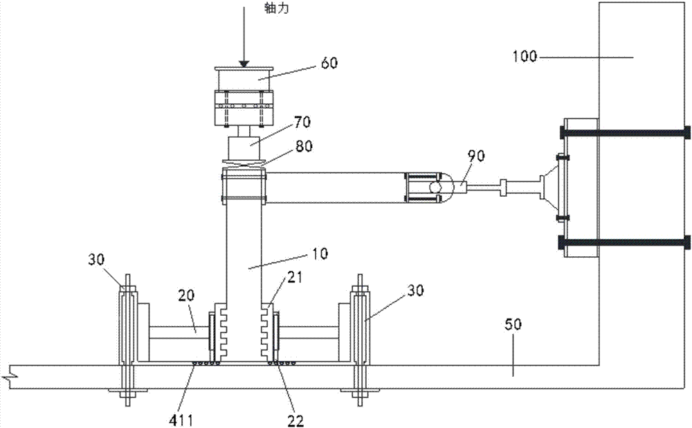
[0026] The main process of the pseudo-static test device for the reinforced concrete column 10 is to arrange the reinforced concrete column 10 to be tested vertically, rigidly fix the bottom of the column, and generate pressure through the vertical pressure device 70 fixed on the reaction beam 60. For vertical compressive stress, through the steel hinge 80 device, a uniform load is applied to the reinforced concrete column 10 specimens according to the test design axial compression ratio. The reinforced concrete column 10 is connected to the laboratory reaction wall 100 through the actuator 90 , and the actuator applies a horizontal reciprocating force to the reinforced concrete column 10 to generate a displacement cycle at the top of the reinforced concrete column 10 . Record the required data with corresponding measuring instruments.

[0027] Compared with the traditional method of setting a huge base at the bottom of the reinforced concrete column 10 to achieve the predeter...

Embodiment 2

[0035] The main process of the traditional pseudo-static test device for reinforced concrete column 10 is to arrange the reinforced concrete column 10 to be tested vertically, rigidly fix the bottom of it, and generate pressure through the vertical pressure device fixed on the reaction beam. For the vertical compressive stress, through the steel hinge device, a uniform load is applied to the reinforced concrete column 10 specimens according to the test design axial compression ratio. The reinforced concrete column 10 is connected to the reaction wall of the laboratory through an actuator, and the actuator applies a horizontal reciprocating force to the reinforced concrete column 10 so that the top of the reinforced concrete column 10 produces a displacement cycle. Record the required data with corresponding measuring instruments.

[0036] The structural cost of setting the base at the bottom of the reinforced concrete column 10 is too high, and the waste is too serious. This e...


PUM


Abstract

The invention relates to the technical fields of building structure experimental device and method, and discloses a quasi-static test device for a base-free reinforced concrete column, wherein the quasi-static test device includes an experimental reinforced concrete column and a rigid connection fixer; the lower end of the reinforced concrete column is not provided with a base and forms a rigid connection part; the rigid connection fixer is fixedly connected onto a ground beam and includes a jack mechanism; the jack mechanism transversely presses against the rigid connection part, so that thelower end of the reinforced concrete column forms a rigid connection state. The structure arrangement makes a reinforced concrete square column test specimen convenient to pour, the stages of column base template preparation, steel reinforcement cage preparation, concrete pouring, maintenance and the like are omitted, and the amount of reinforcing steel bars and the concrete material are saved. Atthe same time, because a jack is used for positioning the reinforced concrete, the device can be used repeatedly and can be adaptive to column components with different sizes, and the cost of experiments is greatly saved.

Description

technical field [0001] The invention relates to the technical field of building structure experiment devices and methods, in particular to a pseudo-static test device and method for a reinforced concrete column without a base. Background technique [0002] In recent years, earthquakes have occurred frequently in our country, and the collapse of building structures caused by earthquakes has caused huge economic losses to our country and seriously threatened the safety of people's lives. In order to study the response of structures under earthquakes, corresponding experimental research is essential, and in structural seismic tests, pseudo-static tests (horizontal low-cycle repeated loading) are often used to simulate the situation of lateral force-resistant structures subjected to earthquakes. [0003] At present, in the quasi-static test of reinforced concrete columns, it is necessary to pour a base at the bottom of the reinforced concrete column whose volume and mass are muc...

Claims


Application Information

Patent Timeline
IPC IPC(8): G01N3/02
CPCG01N3/02Y02E10/50
Inventor 于晓辉代旷宇吕大刚周洲
Owner HARBIN INST OF TECH
Why Eureka
Try Eureka