
Image Dehazing Method Based on Orthogonal Polarization Image Stretching and Polarization Degree Correlation

An orthogonal polarization and image stretching technology, applied in image enhancement, image data processing, instruments, etc., can solve the problems of general effect of scattering medium, deviation of light intensity distribution of reflected light from objects, etc., and reduce light intensity modulation effect , Improve the clarity, the effect is obvious

Active Publication Date: 2020-04-10
TIANJIN UNIV
View PDF4 Cites 0 Cited by
  • Summary
  • Abstract
  • Description
  • Claims
  • Application Information

AI Technical Summary

Problems solved by technology

However, in actual situations, the scattering medium (turbid liquid, haze, etc.) has a certain light intensity modulation effect on the object, which causes the acquired light intensity distribution of the reflected light of the object to deviate from the true value.
[0003] The traditional simplified model of polarization imaging has a more obvious restoration effect on low-concentration scattering media, but the effect on stronger scattering media is general.

Method used


Image

  • Image Dehazing Method Based on Orthogonal Polarization Image Stretching and Polarization Degree Correlation
  • Image Dehazing Method Based on Orthogonal Polarization Image Stretching and Polarization Degree Correlation
  • Image Dehazing Method Based on Orthogonal Polarization Image Stretching and Polarization Degree Correlation

Examples


Embodiment

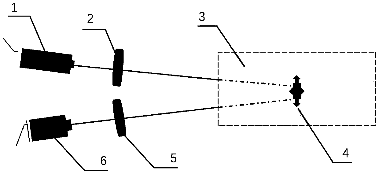
[0077] Such as figure 1 As shown, it is a schematic diagram of the imaging system device in a scattering medium environment (taking turbid underwater as an example). The device is an example of a turbid underwater imaging device based on the incident condition of the light beam of the LED light source involved in the method of the present invention. A polarizer 2 is placed in front of the light source 1 to generate linearly polarized light, a polarization analyzer (PSA) 5 is placed in front of the light intensity detector 3, and the same image can be obtained by rotating the polarization analyzer (PSA) 5 The two polarization states I || and I ⊥ . Use a transparent water tank as a water tank, put milk and clear water in the tank to make it turbid to obtain a scattering medium (turbid water) 3 as a strong scattering environment, and put the detected target object 4 into the scattering medium (turbid water) 3 Among them, the light emitted by the light source 1 is incident on ...


PUM


Abstract

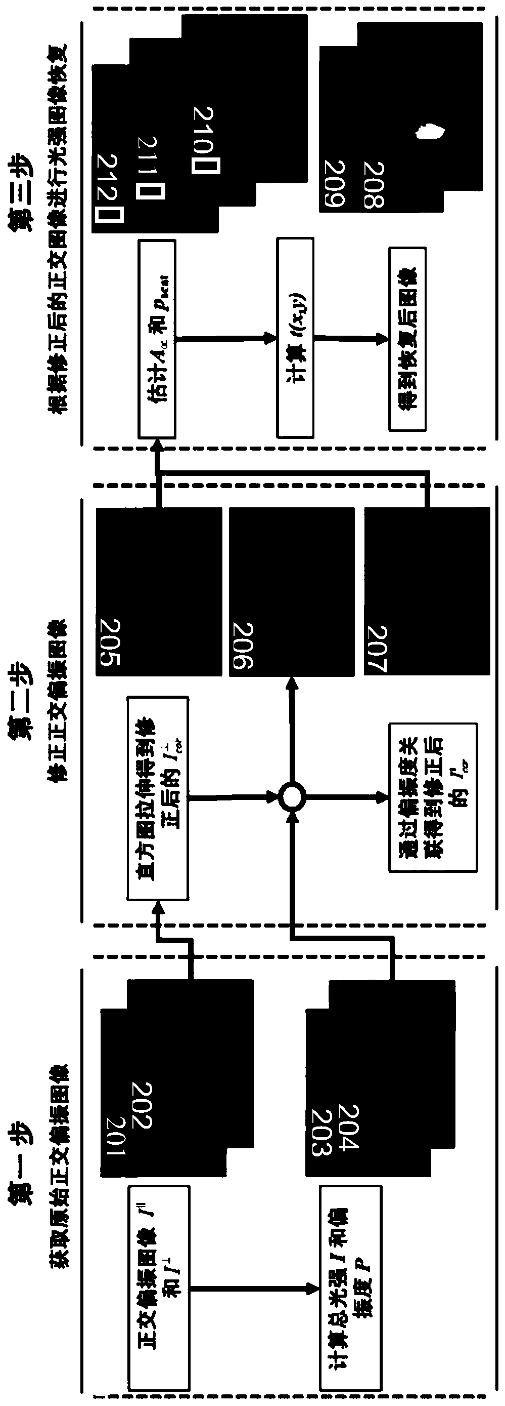
The invention discloses an image defogging method on the basis of cross-polarization image stretching and polarization degree correlation. The image defogging method includes the steps of: 1) acquiring two-time light intensity maps I<parallel> and I<vertical> under cross-polarization status; 2) performing histogram stretching to the light intensity map corresponding to the I<vertical>, thus forming stretch-corrected light intensity map; 3) according to polarization degree correlation, obtaining corrected I<parallel> light intensity map; 4) performing normalization processing to the corrected light intensity information under the two-time cross-polarization status, and respectively performing sum and difference treatment to obtain total light intensity I and polarization difference [delta]I; and 5) performing calculation with a difference polarization restoration model to obtain restoration image. Compared with the prior art, the quality of the restoration image, which is calculated from the corrected cross-polarization light intensity, is improved significantly, so that the method can overcome a defect of poor effect in a strong-scattering environment in the conventional methods and has extensive application range. The method can achieve image restoration only by performing image pre-treatment to the light intensity under the cross-polarization status with combination of a traditional physical model, so that the method has simple operations and significant effects.

Description

technical field [0001] The invention relates to an image defogging and restoration method, in particular to a polarization image defogging method based on orthogonal polarization image grayscale histogram stretching and polarization degree correlation. Background technique [0002] As one of the basic physical information of light waves, polarization information can provide information about the measured object that other light wave information cannot provide. Polarization imaging technology is a new type of optical detection technology developed based on this idea. Especially in strong scattering environments, target detection and recognition based on polarization imaging technology has unique advantages and special applications that cannot be compared with other imaging methods. The foundation of this field is the research of the Schechner group in Israel. It is assumed that the light entering the detector is composed of two parts, one part is the light actually reflected ...

Claims


Application Information

Patent Timeline
Patent Type & Authority Patents(China)
IPC IPC(8): G01N21/21G06T5/00G06T5/40
CPCG01N21/21G06T5/003G06T5/40
Inventor 胡浩丰刘铁根李校博赵琳王辉
Owner TIANJIN UNIV
Learn More