Wide-viewing-angle optical imaging lens system

An optical imaging and lens system technology, applied in the optical field, can solve the problems that the total length cannot be effectively suppressed, the demand for miniaturization cannot be met, and the molding requirements are high.

Active Publication Date: 2018-04-27
GUANGDONG XUYE OPTOELECTRONICS TECH
View PDF8 Cites 3 Cited by
  • Summary
  • Abstract
  • Description
  • Claims
  • Application Information

AI Technical Summary

Problems solved by technology

The traditional four-element and five-element lens structures have limitations in terms of refractive power distribution, aberration astigmatism correction, sensitivity distribution, etc., and cannot further meet higher-level imaging requirements
The current mainstream is the further developed six-piece wide-angle imaging optical lens group, but the increase in the number of lenses increases the total length of the lens, which cannot effectively suppress the total length of the lens group
For example, as shown in US Patent No. US20150177484A1, although its F.no aperture value reaches 2.0, which ensures a large amount of light entering the system, its total length cannot be effectively suppressed, reaching 10mm. Furthermore, its field of view The maximum is only 100°, which cannot meet the needs of modern mobile electronic devices for a large field of view in terms of performance; another example is the patent of the US Patent Publication No. US9488806. The total length of the system far exceeds 10mm, which cannot meet the needs of miniaturization, and it uses glass materials, which have high requirements for molding, which is not conducive to large-scale mass production

Method used


Image

  • Wide-viewing-angle optical imaging lens system
  • Wide-viewing-angle optical imaging lens system
  • Wide-viewing-angle optical imaging lens system

Examples


Embodiment 1

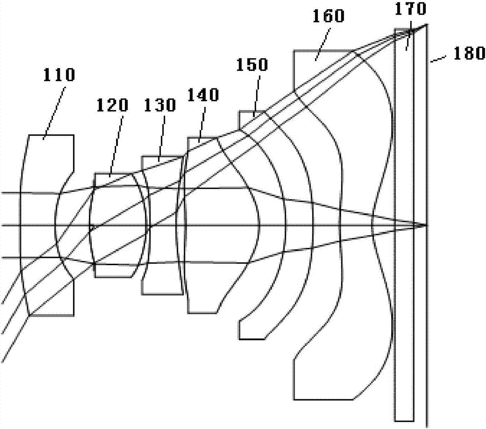
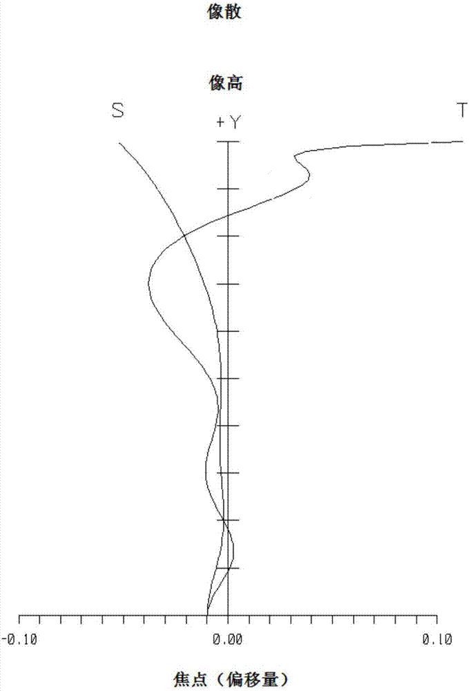
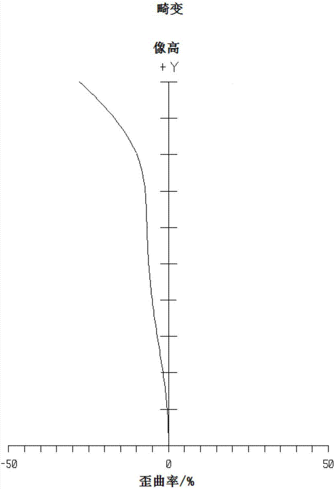
[0103] Such as figure 1 As shown, the wide viewing angle optical imaging lens system of Embodiment 1 includes in sequence from the object side to the image side: a first lens 110, a second lens 120, a third lens 130, a fourth lens 140, a fifth lens 150, and a sixth lens 160 , an infrared filter 170 and an imaging surface 180 . Figure 2a Astigmatism curve diagram provided for Embodiment 1 of the present invention; Figure 2b Distortion curve diagram provided for Embodiment 1 of the present invention; Figure 2c The spherical aberration curve diagram provided for Embodiment 1 of the present invention; the dominant wavelength of the above-mentioned astigmatism, distortion and spherical aberration curve diagram is 0.55um.

[0104] Further illustrate, the material of the first lens 110 is plastic, has negative refractive power, and the image side is concave; the material of the second lens 120 is plastic, has positive refractive power, and both the object side and the image side...

Embodiment 2

[0118] Such as image 3 As shown, the wide viewing angle optical imaging lens system of Embodiment 2 includes in sequence from the object side to the image side: a first lens 210, a second lens 220, a third lens 230, a fourth lens 240, a fifth lens 250, and a sixth lens 260 , an infrared filter 270 and an imaging surface 280 . Figure 4a Astigmatism curve diagram provided for Embodiment 2 of the present invention; Figure 4b Distortion curve diagram provided for Embodiment 2 of the present invention; Figure 4c The spherical aberration curve diagram provided for the second embodiment of the present invention; the dominant wavelength of the above-mentioned astigmatism, distortion and spherical aberration curve diagram is 0.55um.

[0119] Further illustrate, the material of the first lens 210 is plastic, has negative refractive power, and the image side is concave; the material of the second lens 220 is plastic, has positive refractive power, and the object side and the image ...

Embodiment 3

[0130] Such as Figure 5 As shown, the wide viewing angle optical imaging lens system of Embodiment 3 includes in sequence from the object side to the image side: a first lens 310, a second lens 320, a third lens 330, a fourth lens 340, a fifth lens 350, and a sixth lens 360, an infrared filter 370 and an imaging surface 380. Figure 6a Astigmatism curve diagram provided for Embodiment 3 of the present invention; Figure 6b Distortion curve diagram provided for Embodiment 3 of the present invention; Figure 6c The spherical aberration curve diagram provided for the third embodiment of the present invention; the dominant wavelength of the above-mentioned astigmatism, distortion and spherical aberration curve diagram is 0.55um.

[0131] Further illustrate, the material of the first lens 310 is plastic, has negative refractive power, and the image side is concave; the material of the second lens 320 is plastic, has positive refractive power, and both the object side and the ima...


PUM


Abstract

The invention discloses a wide-viewing-angle optical imaging lens system which comprises a first lens having negative refractive power, wherein the image side surface of the first lens is a concave surface; a second lens having positive refractive power; a third lens having negative refractive power, wherein the object side surface and the image side surface of the third lens are concave surfaces;a fourth lens having positive refractive power, wherein the object side surface of the fourth lens is a concave surface near the optical axis and comprises at least one convex surface in the off-axisposition; a fifth lens having refractive power; and a sixth lens having refractive power, wherein the object side surface is a convex surface in the optical axis, the image side surface is a concavesurface in the optical axis, and the object side surface and the image side surface respectively comprise at least one point of inflexion. The first lens, the second lens, the third lens, the fourth lens, the fifth lens and the sixth lens are arranged from the object side to the image side in turn and meet the relational expressions: AG45<0.3, AG56<0.3 and SAG42-SAG41>0.3. The reasonable surface structure and space distribution between the lenses are adopted, the total length of the system can be effectively limited under the condition of wide viewing angle, and the aperture is large so that more quantity of incident light can be realized in imaging and the imaging quality can be enhanced.

Description

technical field [0001] The invention relates to the field of optical technology, in particular to a wide viewing angle optical imaging lens system. Background technique [0002] With the recent rapid development of technology, especially electronic technology, mobile and portable electronic devices have been rapidly popularized. The popularization of electronic devices has resulted in vigorous development of modules such as optical imaging lenses and sensors included therein. At the same time, the application of imaging modules has been more and more widely used, such as smart phones, tablet computers, driving recorders, sports cameras, etc., which are now highly popular. While bringing great convenience to life, people's requirements for mobile electronic device terminals are getting higher and higher, and they are constantly pursuing more convenient, efficient and high-quality mobile experience, which requires mobile terminals to be thinner, lighter and more portable. In...

Claims


Application Information

Patent Timeline
Patent Type & Authority Applications(China)
IPC IPC(8): G02B13/00G02B13/06
CPCG02B13/0045G02B13/06
Inventor 林肖怡李光云王义龙
Owner GUANGDONG XUYE OPTOELECTRONICS TECH
Why Eureka
Try Eureka