an optical camera

A camera and camera lens technology, applied in the field of optical cameras, can solve problems such as high molding requirements, unfavorable large-scale mass production, and inability to meet the needs of miniaturization. Effect

Active Publication Date: 2019-10-25
GUANGDONG XUYE OPTOELECTRONICS TECH
View PDF7 Cites 0 Cited by
  • Summary
  • Abstract
  • Description
  • Claims
  • Application Information

AI Technical Summary

Problems solved by technology

The traditional five-element lens structure has limitations in terms of refractive power distribution, aberration astigmatism correction, sensitivity distribution, etc., and cannot further meet higher-level imaging requirements
The current mainstream is the further developed six-piece wide-angle imaging optical lens group, but the increase in the number of lenses increases the total length of the lens, which cannot effectively suppress the total length of the lens group
For example, as shown in US Patent No. US20150177484A1, although its F.no aperture value reaches 2.0, which ensures a large amount of light entering the system, its total TTL length cannot be effectively suppressed, reaching 10mm. Moreover, its field of view The maximum angle of view is only 100°, which cannot meet the needs of modern mobile electronic devices for a large field of view in terms of performance; another example is the patent of US Patent No. US9488806. The total length of the system far exceeds 10mm, which cannot meet the needs of miniaturization, and it uses glass materials, which have high requirements for molding, which is not conducive to large-scale mass production

Method used


Image

  • an optical camera
  • an optical camera
  • an optical camera

Examples


Embodiment 1

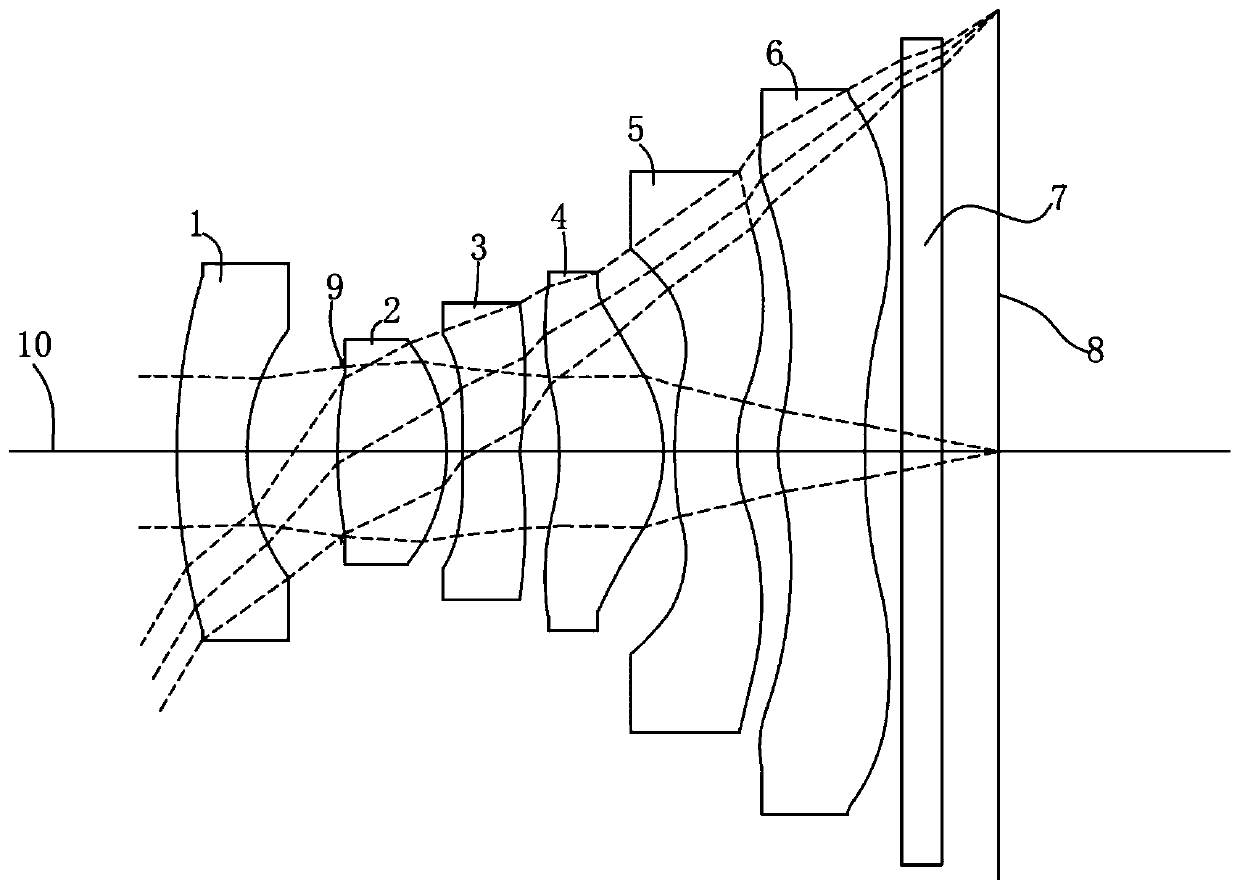
[0045] The invention is a camera used in electronic products. See figure 1 As shown, this is a schematic structural diagram of Embodiment 1 of the present invention. The camera lens is along its optical axis 10 from the object side to the image side direction (i.e. figure 1 shown in the left-to-right direction) include, in order:

[0046] A first lens 1 with negative refraction power, whose image side is concave; this helps light with a larger viewing angle to enter the imaging lens system to provide a wider viewing angle;

[0047] A second lens 2 with positive refractive power, the object side is convex, and the image side is convex; it can provide the positive refractive power of the camera lens and correct the aberration of some systems;

[0048] A third lens 3 with refractive power, the object side is concave near the optical axis, and the image side is also concave near the optical axis, which can correct the astigmatism of some systems and improve the imaging quality; ...

Embodiment 2

[0102] See Figure 5-Figure 8 As shown, this is the second embodiment of the present invention.

[0103] The structure of the second embodiment is the same as that of the first embodiment above. Specifically, as shown in the following table 2-1, the specification parameters of the components of the second embodiment are as follows:

[0104]

[0105]

[0106] Similarly, in the second embodiment, the object-side surface and the image-side surface of all lenses are aspherical, and the aspheric coefficients of each lens are shown in Table 2-2.

[0107]

[0108] Combined with the following table 2-3, this is the condition that the lens assembly in the second embodiment needs to meet:

[0109]

[0110] As shown in Table 2-3, compared with the first embodiment above, the specific parameters of the conditions to be met in the second embodiment are adjusted within the conditional range.

[0111] After the above-mentioned technical conditions are adopted in the second emb...

Embodiment 3

[0113] See Figure 9-Figure 12 As shown, this is the third embodiment of the present invention, and the third embodiment has the same structure as the above-mentioned embodiment. As shown in the following table 3-1, the specification parameters of each component of the present embodiment three are as follows:

[0114]

[0115]

[0116] Similarly, in the third embodiment, the object-side surface and the image-side surface of all lenses are aspherical, and the specific aspheric coefficients of each lens are shown in Table 3-2.

[0117]

[0118] Combined with the following table 3-3, this is the condition that the lens assembly in the third embodiment needs to meet:

[0119]

[0120] As shown in Table 4-3, compared with the above-mentioned embodiments, the specific parameters of the conditions to be met in the third embodiment are adjusted within the condition range.

[0121] After the above-mentioned technical conditions are adopted in the third embodiment, the focal...


PUM


Abstract

The invention discloses an optical camera which comprises a first lens with negative refraction power, a second lens with positive refraction power, a third lens with refraction power, a fourth lens with refraction power, a fifth lens with negative refraction power and a sixth lens with refraction power in sequence from the object side to the image side along the optical axis of the camera. The object side face of the second lens is a convex face, the image side face of the second lens is a convex face, the position, close to the optical axis, of the object side face of the fifth lens is a convex face, the position, close to the optical axis, of the image side face of the fifth lens is a concave face, the position, outward away from the optical axis, of the concave face of the fifth lens is provided with at least one convex face, the position, close to the optical axis, of the image side face of the sixth lens is a concave face, and the position, away from the optical axis, of the image side face of the sixth lens is provided with at least one inflection point. The optical camera meet the condition that (R51+R52) / (R51-R52) is larger than 1.8 and smaller than 4. By means of the technical scheme, through the reasonable profile structure and proper lens internal distribution, the best optimization is conducted on a system. The large field angle is obtained, the total length of thesystem can be effectively restrained, the current light and portable requirements are met.

Description

Technical field: [0001] The invention relates to the technical field of optical camera products, in particular to an optical camera used in various electronic products. Background technique: [0002] With the recent rapid development of technology, especially electronic technology, mobile and portable electronic devices have been rapidly popularized. The popularity of electronic devices has led to the vigorous development of modules such as optical imaging lenses and impact sensors included in them. At the same time, the application of imaging modules has been more and more widely used, such as smart phones, tablet computers, driving recorders, sports cameras, etc., which are now highly popular. [0003] While bringing great convenience to life, people's requirements for mobile electronic device terminals are getting higher and higher, and they are constantly pursuing more convenient, efficient and high-quality mobile experience, which requires mobile terminals to be thinne...

Claims


Application Information

Patent Timeline
Patent Type & Authority Patents(China)
IPC IPC(8): G02B13/00G02B13/18
CPCG02B13/0045G02B13/18
Inventor 林肖怡袁正超
Owner GUANGDONG XUYE OPTOELECTRONICS TECH
Why Eureka
Try Eureka