Plane-revolution reversible glasses

A plane rotating and flipping mirror technology, which is applied in medical science, eye testing equipment, eye exerciser, etc., can solve the problems of inconvenient operation of hand-held flip mirrors, uncertain lens distances, and unfixed distances, etc., to achieve improved The effect of adjusting sensitivity and inspection accuracy, precisely adjusting the number of cycles, and reducing operating time

Active Publication Date: 2018-05-01
重庆能能科技有限公司
View PDF14 Cites 4 Cited by
  • Summary
  • Abstract
  • Description
  • Claims
  • Application Information

AI Technical Summary

Problems solved by technology

[0003] The flipping of the existing flip mirror has the following disadvantages: 1. It is inconvenient to operate the flip mirror by hand, and it is easy to cause the subject to fail to see the visual mark through the lens during the flipping process, which will also cause the distance between the eyes and the lens and the distance of the visual mark. The distance between the eyes is not fixed and the inspection cannot be standardized, and there is a delay in the operation time during the completion of the flipping process. These factors may cause technical inspection errors; Human errors are prone to human error when flipping times per unit time, and it is difficult to accurately record the user's adjustment time, resulting in inaccurate inspection results; and the existing timing and counting is only a statistics of the adjustment cycle per unit time, and it is impossible to clearly record positive adjustment or How long does negative adjustment take
3. When adjusting the sensitivity of the existing flip mirror training, the arm is prone to fatigue when the flip mirror is operated by hand, resulting in an uncertain distance between the eyes and the lens, and factors such as the misalignment between the optical center of the lens and the pupil center of the eye affect the training effect

Method used


Image

  • Plane-revolution reversible glasses
  • Plane-revolution reversible glasses
  • Plane-revolution reversible glasses

Examples


Embodiment 1

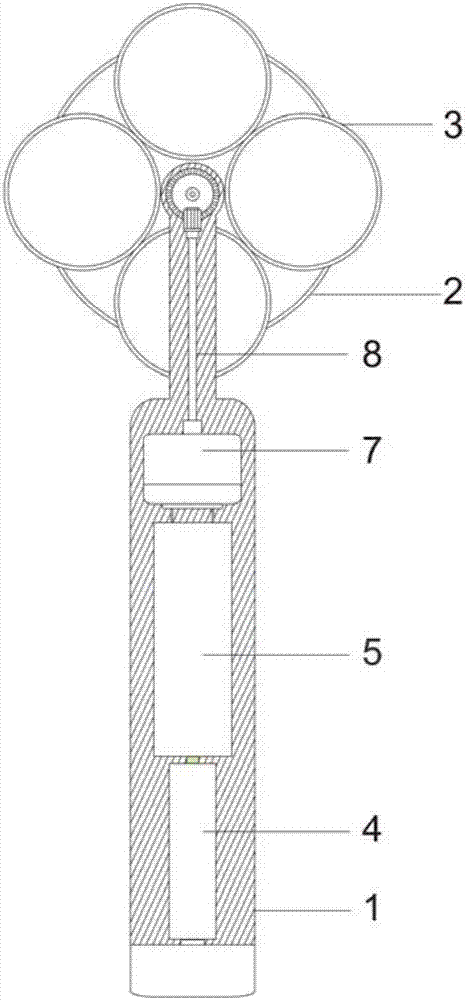
[0033] figure 1 The back sectional view of a kind of plane rotating flip mirror prepared for embodiment 1;

[0034] figure 2 The front sectional view of a kind of planar rotating flip mirror prepared for embodiment 1;

[0035] Figure 7 A side sectional view of a kind of planar rotating flip mirror designed for embodiment 1; wherein A is an overall view, and B is an enlarged view of a transmission mechanism;

[0036] like figure 1 and figure 2 As shown, a plane rotating flip mirror includes a handle 1 and a lens frame 2. The handle handle is a thin shell cavity structure, and a transmission system and a control system are arranged inside. The lens frame is connected to the transmission system and is arranged on At the upper end of the handle, the lens frame is parallel to the axial plane of the handle. The control system controls the transmission system to drive the lens frame to rotate on this plane. The lens frame is composed of four lens frames 3, and the centers of ...

Embodiment 2

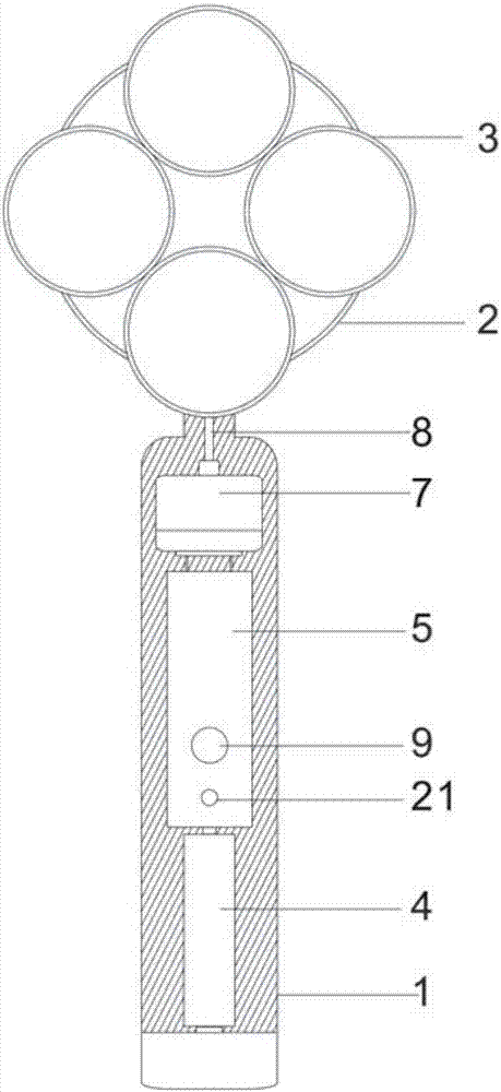
[0041] image 3 A kind of plane rotating flip mirror prepared for embodiment 2;

[0042] Figure 4 A schematic diagram of the use of a plane rotating flip mirror prepared in Example 2;

[0043] like image 3 and Figure 4 As shown, a plane rotating flip mirror includes a handle 1 and a lens frame 2. The handle handle is a thin shell cavity structure, and a transmission system and a control system are arranged inside. The lens frame is connected to the transmission system and is arranged on At the upper end of the handle, the lens frame is parallel to the axial plane of the handle. The control system controls the transmission system to drive the lens frame to rotate on this plane. The lens frame is composed of four lens frames 3, and the centers of the four lens frames are located at the center of the lens frame. On the same circle of , the plane rotation is the circular movement of the four lenses around the center of the lens frame;

[0044] Preferably, the control syste...

Embodiment 3

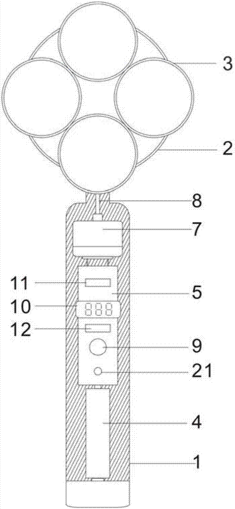
[0052] Figure 5 A schematic diagram of the use of a plane rotating flip mirror designed for embodiment 3;

[0053] A plane rotating reversible mirror, comprising a handle 1 and a lens frame 2, the handle is provided with a transmission system and a control system, the lens frame is connected to the transmission system and is arranged on the upper end of the handle, the axial plane between the lens frame and the handle Parallel, the control system controls the transmission system to drive the lens frame to rotate on this plane, the lens frame is composed of four lens frames 3, the centers of the four lens frames are located on the same circle centered on the center of the lens frame, and the plane rotates into four lenses Circular motion around the center of the lens frame;

[0054] Preferably, the control system includes a power switch 21, a control switch 9, a PCB control board 5, a stepper motor 7 and a power supply 4, and the PCB control board is also provided with a timi...


PUM


Abstract

The invention relates to plane-revolution reversible glasses. The plane-revolution reversible glasses comprise a handle and a lens frame, the handle is internally provided with a transmission system and a control system, the lens frame is connected with the transmission system and arranged at the upper end of the handle, the lens frame and the axial surface of the handle are in parallel, the control system controls the transmission system to drive the lens frame to rotate in the plane, the lens frame is composed of four lens frame bodies which are provided with lenses, the centers of the fourlens frame bodies are located on the same circumference taking the center of the lens frame as the center, and plane revolution means circular motion of the four lenses around the center of the lens frame. By adopting the plane-revolution reversible glasses, to a certain degree, it is guaranteed that the distances between eyes and the lenses and the distances between sighting targets and the eyesare fixed, so that operation time for completing a lens reversal process is shortened, and the precision of testing and training is improved; furthermore, the plane-revolution reversible glasses are in combination with electronic recording of regulation periods, so that not only are errors brought by manual reversal and timekeeping reduced, but also the number of the regulation periods per unit time is counted more precisely, and the accuracy of sensitivity regulation testing is greatly improved.

Description

technical field [0001] The invention relates to an instrument for visual adjustment sensitivity inspection and training, in particular to a plane rotating flip mirror. Background technique [0002] With the increase in the frequency of use of video terminals, more and more myopia. During the critical period of development, many adolescents and children experience eye fatigue and abnormal adjustment function due to the long time of using their eyes at close range, which leads to myopia. In medicine, the adjustment function of the eye is mainly evaluated from two aspects: the adjustment range and the adjustment sensitivity, and the inspection of the adjustment sensitivity will use a flip mirror. The existing flip mirror is composed of four lenses connected in series by a central axis. One side of the central axis is two positive mirrors, and the other side is two negative mirrors. When in use, the rotation of the central axis drives the positive and negative lens groups to fl...

Claims


Application Information

Patent Timeline
Patent Type & Authority Applications(China)
IPC IPC(8): A61B3/09A61H5/00
CPCA61B3/09A61H5/00
Inventor 陈小荣汪春露王文文
Owner 重庆能能科技有限公司
Why Eureka
Try Eureka