Positioning device for globar machining

A technology of positioning device and silicon carbon rod, which is applied in the direction of fine working devices, stone processing equipment, working accessories, etc., can solve the problems of inability to quickly and accurately locate, affect work efficiency, and lack of positioning devices, so as to avoid efficiency reduction and operation Simple, easy-to-use effects

Inactive Publication Date: 2018-05-01
河南格锐新材料科技有限公司
View PDF0 Cites 6 Cited by
  • Summary
  • Abstract
  • Description
  • Claims
  • Application Information

AI Technical Summary

Problems solved by technology

[0003] The purpose of the present invention is to solve the problem that the existing cutting or drilling device in the prior art lacks a positioning device, which causes the user to be unable to quickly and accurately position when cutting or drilling, and affects work efficiency. A positioning device for carbon silicon rod processing

Method used


Image

  • Positioning device for globar machining
  • Positioning device for globar machining

Examples


Embodiment Construction

[0014] The following will clearly and completely describe the technical solutions in the embodiments of the present invention with reference to the accompanying drawings in the embodiments of the present invention. Obviously, the described embodiments are only some, not all, embodiments of the present invention.

[0015] In describing the present invention, it should be understood that the terms "upper", "lower", "front", "rear", "left", "right", "top", "bottom", "inner", " The orientation or positional relationship indicated by "outside", etc. is based on the orientation or positional relationship shown in the drawings, and is only for the convenience of describing the present invention and simplifying the description, rather than indicating or implying that the referred device or element must have a specific orientation, so as to Specific orientation configurations and operations, therefore, are not to be construed as limitations on the invention.

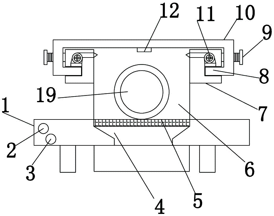
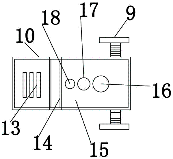
[0016] refer to Figure ...


PUM


Abstract

The invention discloses a positioning device for globar machining. The positioning device comprises a base and a moving shield plate, wherein supporting legs are mounted at both the left and right ends of the bottom of the base; a switch button is arranged at the left end of the base; a control switch is arranged below the switch button, a fixing tank is fixedly connected with the top of the base;a filter screen is arranged at the joint between the fixing tank and the base; a dust hopper is arranged inside the base; a dust collecting tank is arranged at the bottom of the base; and a clampinghole is formed inside the fixing tank. According to the positioning device, a sliding rail is arranged on supporting frames, sliding blocks are arranged at the bottoms of both the left and right endsof the moving shield plate, and the sliding blocks and the sliding rail are slidably connected, so that the specific positon of the moving shield plate can be freely adjusted as required and the use can be facilitated; air outlet pipes of miniature air blowing devices are fixedly connected with the inner wall of the fixing tank, so that dust generated during the cutting or grinding action of a user can be cleared through air blown by the miniature air blowing devices; and the positioning device is simple to operate and convenient to use.

Description

technical field [0001] The invention relates to a positioning device, in particular to a positioning device for processing silicon carbon rods. Background technique [0002] At present, carbon silicon rods are colorless cubic or hexagonal crystals, and the surface is blue-black when oxidized or contains impurities. Silicon carbon rods have a three-dimensional spatial structure composed of silicon atoms and carbon atoms, and each atom is surrounded by other four atoms. There are many variants of carbon silicon rods, most of which are diamond, sphalerite and fiberite lattices. Under the current market conditions, the demand for carbon silicon rods has a high index. The existing carbon silicon rods are in order to adapt to the market. The demand usually requires cutting and drilling, but there is a lack of a positioning device in the existing cutting or drilling devices, which makes the user unable to quickly and accurately position when cutting or drilling, which affects work...

Claims


Application Information

Patent Timeline
Patent Type & Authority Applications(China)
IPC IPC(8): B28D5/00B28D5/02B28D7/02
CPCB28D5/021B28D5/0058B28D5/0076
Inventor 胡耀伟
Owner 河南格锐新材料科技有限公司
Why Eureka
Try Eureka