Dispensing equipment and method for preparing high thermal conducting interface material by adopting dispensing equipment

A kind of equipment and glue dispensing technology, which is applied in the field of preparing high thermal conductivity interface materials, can solve the problems of difficult cutting of flexible materials, difficult and large size of products, etc., and achieve the effect of excellent thermal conductivity, low cost and optimized process parameters

Active Publication Date: 2018-05-01
彗艺新材料科技(佛山)有限公司
View PDF5 Cites 2 Cited by
  • Summary
  • Abstract
  • Description
  • Claims
  • Application Information

AI Technical Summary

Problems solved by technology

The invention patent with the publication number CN103975429A discloses a qualitative arrangement of carbon fibers by means of extrusion. This method needs to be cut into thin slices after extrusion, but it is difficult to cut flexible materials, and it is difficult to make large-scale products.

Method used


Image

  • Dispensing equipment and method for preparing high thermal conducting interface material by adopting dispensing equipment
  • Dispensing equipment and method for preparing high thermal conducting interface material by adopting dispensing equipment
  • Dispensing equipment and method for preparing high thermal conducting interface material by adopting dispensing equipment

Examples


Embodiment 1

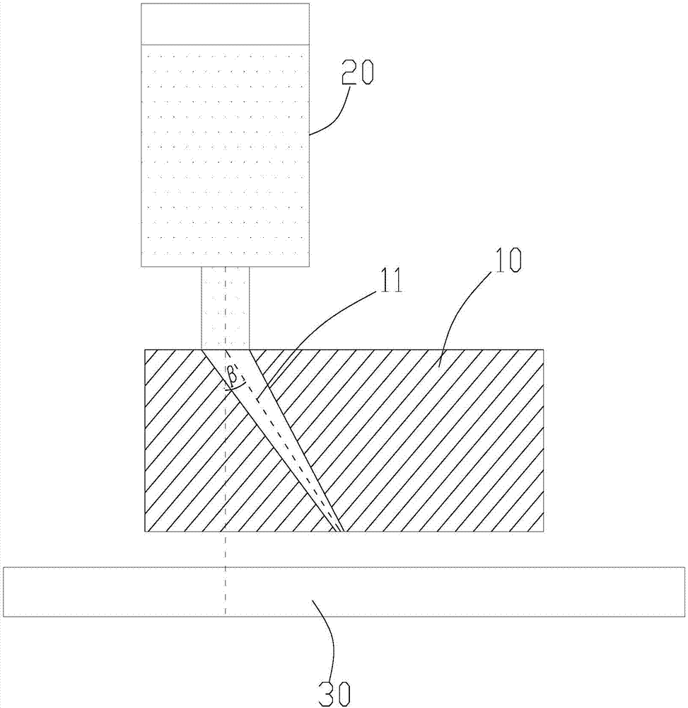
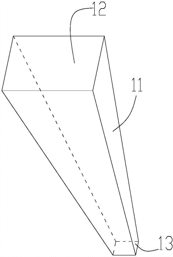
[0047] refer to Figure 1-3, a dispensing device, comprising a dispensing mold 10; the dispensing mold 10 is provided with a glue extrusion channel 11; the glue extrusion channel 11 includes a glue extrusion channel inlet 12 and a through dispensing Outlet 13 of the extrusion channel on the bottom surface of the mold, the cross-sectional area of ​​the extrusion channel gradually decreases from top to bottom; an angle β is formed between the central axis of the extrusion channel and a vertical line, and β is 45°.

[0048] Glue dispensing equipment also comprises the glue barrel 20 that is arranged on the glue dispensing mold 10 tops, and the discharge port of described glue barrel 20 is connected with described extrusion channel inlet, and their cross-sectional area is identical; The cross-section of described glue barrel The area is A1, the cross-sectional area A2 of the inlet of the dispensing mold, and the cross-sectional area A3 of the outlet of the dispensing mold, A1:A2=4...

Embodiment 2

[0054] A dispensing device, comprising a dispensing mold; the dispensing mold is provided with a glue extrusion channel; the glue extrusion channel includes a glue extrusion channel inlet that runs through the top surface of the glue dispensing mold and a glue extrusion channel that runs through the bottom surface of the glue dispensing mold At the outlet, the cross-sectional area of ​​the extruding channel gradually decreases from top to bottom; the central axis of the extruding channel forms an angle β with a vertical line, and β is 30°.

[0055] The dispensing equipment also includes a glue barrel arranged above the glue dispensing mold, the discharge port of the glue barrel is connected with the entrance of the extrusion channel, and their cross-sectional area is the same; the cross-sectional area of ​​the glue barrel is A1 , the cross-sectional area A2 of the inlet of the dispensing mold, the cross-sectional area A3 of the outlet of the dispensing mold, A1:A2=5:1; A2:A3=8:...

Embodiment 3

[0061] A dispensing device, comprising a dispensing mold; the dispensing mold is provided with a glue extrusion channel; the glue extrusion channel includes a glue extrusion channel inlet that runs through the top surface of the glue dispensing mold and a glue extrusion channel that runs through the bottom surface of the glue dispensing mold At the outlet, the cross-sectional area of ​​the extrusion channel gradually decreases from top to bottom; the central axis of the extrusion channel forms an angle β with a vertical line, and β is 60°.

[0062] The dispensing equipment also includes a glue barrel arranged above the glue dispensing mold, the discharge port of the glue barrel is connected with the entrance of the extrusion channel, and their cross-sectional area is the same; the cross-sectional area of ​​the glue barrel is A1 , the cross-sectional area A2 of the inlet of the dispensing mold, the cross-sectional area A3 of the outlet of the dispensing mold, A1:A2=6:1; A2:A3=16...


PUM


Abstract

The invention discloses dispensing equipment, and further discloses a method for preparing a high thermal conducting interface material by adopting the dispensing equipment. The dispensing equipment comprises a dispensing die. The dispensing die is provided with a glue extruding channel. The glue extruding channel comprises a glue extruding channel inlet penetrating through the top surface of thedispensing die and a glue extruding channel outlet penetrating through the bottom surface of the dispensing die. The cross section area of the glue extruding channel decreases gradually from top to bottom. An included angle beta being 30-90 degrees is formed between the center axis of the glue extruding channel and a vertical line. The dispensing equipment has the characteristics that the structure is simple, the cost is low, and directional arrangement of carbon fiber can be achieved; the method can achieve directional arrangement of the carbon fiber, manufacturing of a large area of the highthermal conducting interface material can be achieved, and the high thermal conductivity interface material manufactured and obtained by adopting the method has excellent thermal conducting performance.

Description

technical field [0001] The invention relates to a glue dispensing equipment, in particular to a glue dispensing equipment and a method for preparing a high thermal conductivity interface material by using the glue dispensing equipment. Background technique [0002] The performance of electronic components will be degraded or damaged due to overheating, so the cooling of electronic components has become an important issue. For the thermal interface material used between the heating element and the radiator, it is often required to have excellent thermal conductivity. [0003] In the prior art, the invention patent with the publication number CN100548099C discloses a method for aligning carbon fibers by using a magnetic field. This method requires an ultra-high magnetic field strength (above 1T), and the equipment is difficult to manufacture and expensive. The environment is harsh and requires a non-magnetic environment to avoid accidental injury. The invention patent with t...

Claims


Application Information

Patent Timeline
Patent Type & Authority Applications(China)
IPC IPC(8): B29C70/50B29C70/12B29L31/34
CPCB29C70/12B29C70/50B29L2031/3406
Inventor 徐峰
Owner 彗艺新材料科技(佛山)有限公司
Why Eureka
Try Eureka