Combined pump-jet propeller

A propulsion and combined technology, applied in ship propulsion, propulsion parts, ship parts, etc., can solve the problems of high noise, energy loss, low propulsion efficiency, etc., and achieve low radiation noise, low thrust loss, and high propulsion efficiency. Effect

Pending Publication Date: 2018-05-01
裴睿涛
View PDF13 Cites 6 Cited by
  • Summary
  • Abstract
  • Description
  • Claims
  • Application Information

AI Technical Summary

Problems solved by technology

[0002] At present, water ships and submarines mainly use propellers as mechanical propulsion devices. The propellers are used to convert the rotational power of the engine into propulsion by the rotation of the blades. The disadvantages are low propulsion efficiency and high noise. Although the performance of the water-jet propulsion pump is better than that of the propeller, the rotor of the pump-jet propeller will accelerate the water flow and pass it to the stator for rectification. After the water flow passes through the end of the transmission mechanism, the high-speed edge flow layer on the outside of the flow field will move closer to the center. A low speed zone (low pressure zone) is formed at the end of the transmission mechanism
No matter how high the velocity of the fluid is, this low-pressure area will exist. After a certain distance, the outer high-speed edge flow layer will move closer to this area. After moving closer, friction (wake vortex) will occur between the fluids, resulting in energy loss. Reduce the propulsion efficiency of the pump-jet propeller; the water-jet propulsion pump requires sufficient and relatively stable inflow
Also the water jet propulsion pump is less efficient at low speeds (less than 20 knots)

Method used


Image

  • Combined pump-jet propeller

Examples


Embodiment Construction

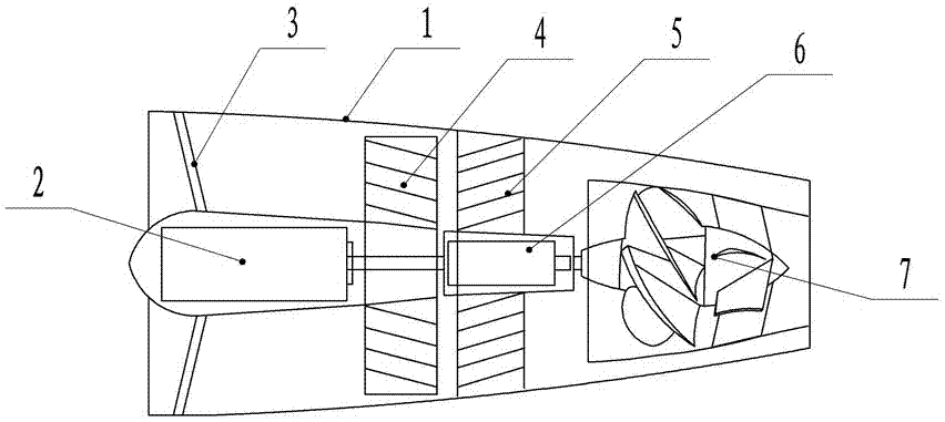
[0009] The combined pump-jet propeller includes an external conduit 1, the external conduit 1 is in a shrinking shape, and the two ends of the external conduit 1 are respectively water inlet and water outlet. The device includes a pump spray rotor 4, a pump spray stator 5 and a pump spray motor 2, the pump spray motor 2 is fixed in the external conduit 1 through four fixed wings 3, the pump spray motor 2 is connected to the pump spray rotor 4 at the rear, and the pump spray rotor 4 The pump spray stator 5 is arranged at the rear for rectification, and the pump spray stator 5 is connected to the external conduit 1. The spray pump impeller motor 6 is arranged at the center of the pump spray stator 5, and the spray pump impeller motor 6 is connected to the water spray propulsion pump 7.

[0010] The present invention adopts the combination of pump-jet propulsion and water-jet propulsion, which avoids the disadvantages of common propeller propulsion such as poor cavitation resistan...


PUM


Abstract

The invention relates to a propeller, specifically to a combined pump-jet propeller. The combined pump-jet propeller is characterized by comprising an external guide pipe; the external guide pipe is of a contracted shape; two ends of the external guide pipe is respectively a water inlet and a water outlet; a pump-jet propeller and a water jet pump are arranged within the combined pump-jet propeller; the pump-jet propeller comprises a pump-jet rotor, a pump-jet stator and a pump-jet motor; the pump-jet motor is fixed within the external guide pipe through four fixed rotors; the rear part of thepump-jet motor is connected with the pump-jet rotor; the pump-jet stator is arranged behind the pump-jet rotor to be used for rectification; the pump-jet stator is connected with the external guide pipe; a pump-jet impeller motor is arranged at the center of the pump-jet stator; and the pump-jet impeller motor is connected with the water jet pump. The combined pump-jet propeller has the advantages that defects of the pump-jet propeller and the water jet pump complement each other on the premise that the advantages of both the pump-jet propeller and the water jet pump are kept; the combined propeller has the advantages of low radiation noise, less thrust loss, higher propelling efficiency and high critical speed; and the combined pump-jet propeller is suitable for submarines and vessels.

Description

technical field [0001] The invention relates to a propeller, in particular to a combined pump-jet propeller. Background technique [0002] At present, water ships and submarines mainly use propellers as mechanical propulsion devices. The propellers are used to convert the rotational power of the engine into propulsion by the rotation of the blades. The disadvantages are low propulsion efficiency and high noise. Although the performance of the water-jet propulsion pump is better than that of the propeller, the rotor of the pump-jet propeller will accelerate the water flow and pass it to the stator for rectification. After the water flow passes through the end of the transmission mechanism, the high-speed edge flow layer on the outside of the flow field will move closer to the center. A low-speed zone (low-pressure zone) is formed at the end of the transmission mechanism. No matter how high the velocity of the fluid is, this low-pressure area will exist. After a certain dista...

Claims


Application Information

Patent Timeline
Patent Type & Authority Applications(China)
IPC IPC(8): B63H11/08
CPCB63H11/08B63H2011/081B63H2011/084
Inventor 裴睿涛
Owner 裴睿涛
Why Eureka
Try Eureka