
Fusible alloy connecting structure and use method thereof for building construction

A technology of fusible alloy and connection structure, which is applied in the direction of building structure, building, building structure support, etc., can solve the problems of lower load-bearing capacity of the support, poor connection stability, loose aluminum alloy support, etc., to achieve good connection stability and improve Load-bearing strength, easy to promote the effect

Active Publication Date: 2018-05-01
云南建投第十六建设有限公司
View PDF6 Cites 0 Cited by
  • Summary
  • Abstract
  • Description
  • Claims
  • Application Information

AI Technical Summary

Problems solved by technology

[0002] At present, in building construction, aluminum alloy brackets are often used to fix equipment or build work platforms. The connection between alloy brackets is traditionally fixed by bolts. For the connection method that requires the connection point to be in the middle of the two brackets, bolts are used. It cannot be realized. For this kind of connection requirements, two matching connectors are usually used for connection and locking. The tightening method mostly adopts the form of rotating buckle. During long-term use of the fixedly connected bracket, the connectors are likely to loosen due to factors such as vibration and impact, and the connection stability is poor, which in turn causes the interconnected aluminum alloy brackets to loosen, resulting in the load bearing of the bracket. Decreased capacity, causing damage to connected and fixed equipment, endangering the life safety of operators

Method used


Image

  • Fusible alloy connecting structure and use method thereof for building construction
  • Fusible alloy connecting structure and use method thereof for building construction

Examples


Embodiment Construction

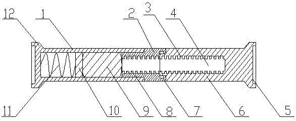
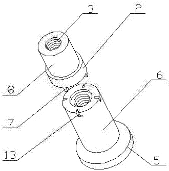
[0016] A fusible alloy connection structure for building construction in the present invention is realized in this way. It consists of a main device and an auxiliary device. The main device consists of a metal pipe (1), a locking sleeve (2), an annular groove (3), and a locking buckle ( 7), connecting sleeve (8), temperature control fusible alloy (9), piston (10), compression spring (11) and limit platform (12), the limit platform (12) is placed in the metal tube (1) On one end, the outer wall of the metal tube (1) is threaded, the piston (10) is placed in the metal tube (1), and is connected with the limit platform (12) through the compression spring (11), and the connecting sleeve (8 ) placed in the other end of the metal tube (1), the inner wall of the connecting sleeve (8) is equally spaced with a plurality of annular grooves (3), and the temperature-controlling fusible alloy (9) is placed in the metal tube (1), And it is located between the piston (10) and one end of the ...


PUM


Abstract

The invention relates to a fusible alloy connecting structure and a use method thereof for building construction, in particular to a connecting structure for internally connecting and fixing two alloyframes through a fusible alloy and the use method thereof. The connecting is more stable; the fusible alloy connecting structure is characterized in that a limiting table is arranged on one end of ametal tube, and a thread is arranged on the outer wall of the metal tube; a piston is disposed in the metal tube, and the piston is connected with the limiting table through a compression spring; a connecting sleeve is disposed at the other end of the metal tube, and a plurality of annular grooves are equidistantly formed in the inner wall of the connecting sleeve; a temperature-control fusible alloy is arranged in the metal tube and is located between the piston and one end of the connecting sleeve, and one end of a locking sleeve is disposed on the other end of the connecting sleeve; a plurality of annular grooves are equidistantly formed in the inner wall of the locking sleeve, a plurality of locking buckles are arranged at equal intervals on the other end of the locking sleeve, and theouter diameter of the locking sleeve is equal to the outer diameter of the metal tube; and a limited block is disposed on one end of a threaded rod, a plurality of locking grooves are equidistantly formed in the other end of the threaded rod, and the locking grooves are in one-to-one correspondence with the multiple locking buckles.

Description

technical field [0001] The invention relates to a fusible alloy connection structure for building construction and a use method thereof, and relates to a structure for connecting two alloy supports used in building construction and a use method thereof, belonging to the field of building construction. In particular, it relates to a connection structure for internally connecting and fixing two alloy brackets through a fusible alloy and a use method thereof. Background technique [0002] At present, in building construction, aluminum alloy brackets are often used to fix equipment or build work platforms. The connection between alloy brackets is traditionally fixed by bolts. For the connection method that requires the connection point to be in the middle of the two brackets, bolts are used. It cannot be realized. For this kind of connection requirements, two matching connectors are usually used for connection and locking. The tightening method mostly adopts the form of rotatin...

Claims


Application Information

Patent Timeline
IPC IPC(8): E04G7/30
CPCE04G7/301
Inventor 不公告发明人
Owner 云南建投第十六建设有限公司
Learn More