Outer fin heat exchange tube and application method thereof

A technology of external fins and heat exchange tubes, applied in the field of high-efficiency and compact heat exchangers, to achieve the effect of variable cross-section design, optimized performance and manufacturing cost, and heat transfer with small temperature difference

Active Publication Date: 2018-05-01
SHANGHAI POWER EQUIP RES INST
View PDF8 Cites 9 Cited by
  • Summary
  • Abstract
  • Description
  • Claims
  • Application Information

AI Technical Summary

Problems solved by technology

[0006] At present, there is no public report on the external finned heat exchange tubes used for full countercurrent heat exchange in the industry.

Method used


Image

  • Outer fin heat exchange tube and application method thereof
  • Outer fin heat exchange tube and application method thereof
  • Outer fin heat exchange tube and application method thereof

Examples


Embodiment 1

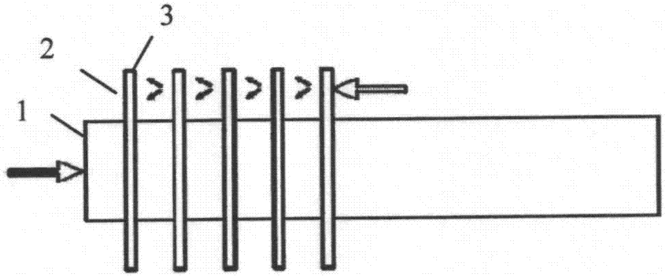
[0040] figure 1 The schematic diagram of the front view of the outer fin heat exchange tube provided in this embodiment, the outer fin heat exchange tube is composed of the following components:

[0041] The heat transfer tube 1 is used to separate the two fluids inside and outside the tube, and realize heat transfer mainly through convection and conduction;

[0042] The outer fin group 2 is used to expand the outer heat exchange surface of the heat transfer tube 1 to form a micro flow channel, restrict the counterflow of the fluid outside the tube along the axial direction of the heat transfer tube 1, and generate a disturbance effect at the same time;

[0043] The outer fin group frame 3 is used to reduce the lateral flow of the fluid outside the heat transfer tube 1 .

[0044] The outer wall of the heat transfer tube 1 is connected with a plurality of outer fin groups 2, and the plurality of outer fin groups 2 are arranged axially along the heat transfer tube 1; the outer ...

Embodiment 2

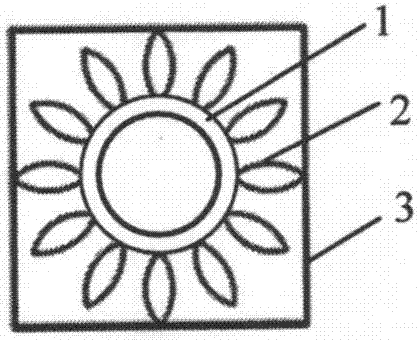
[0050] This embodiment is substantially the same as Embodiment 1, the difference being that the outer fin group 2 is a hollow rectangular frame structure formed of metal sheets or thin strips. A plurality of outer fin groups 2 are arranged around the heat transfer tube 1, and the surface of the outer fin group 2 is parallel to the axial direction of the heat transfer tube to form a symmetrical structure, such as image 3 shown.

Embodiment 3

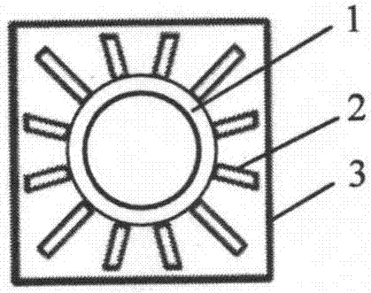
[0052] This embodiment is substantially the same as Embodiment 1, the difference being that the outer fin group 2 is made of thin metal sheets or thin strips, forming a strip structure in which multiple hollow rings are sequentially connected. A plurality of outer fin groups 2 are arranged around the heat transfer tube 1, and the surface of the outer fin group 2 is parallel to the axial direction of the heat transfer tube to form a symmetrical structure, such as Figure 4 shown.


PUM


Abstract

The invention provides an outer fin heat exchange tube, which comprises a heat transfer tube, outer fin groups, and an outer fin group frame. Each outer fin group is used for extending an outside heatexchange surface of the heat transfer tube, forming a micro-channel, restraining an adverse current of an outside tube fluid along an axial direction of the heat transfer tube, and producing a turbulent flow action at the same time; the outer fin group frame is used for reducing transverse flow of the outside tube fluid of the heat transfer tube; an outer wall of the heat transfer tube is connected with the multiple outer fin groups; the outer fin groups are arrayed along an axial direction of the heat transfer tube; holes are formed in the outer fin groups; the holes of the multiple outer fin groups form the micro-channel parallel to the axial direction of the heat transfer tube; and the peripheries of the outer fin groups are connected with the outer fin group frame. The invention further provides an application method of the outer fin heat exchange tube. According to the outer fin heat exchange tube provided by the invention, complete countercurrent flow heat exchange is realized between fluids inside and outside the tube, so that small temperature-difference heat transfer can be realized; when the outside tube fluid passes through the micro-channel structure of the outer fin groups, fins have the sufficient turbulent flow action, so that a convective heat-transfer coefficient is improved; and the outer fin heat exchange tube can be used for manufacturing a high-efficient and compact heat exchanger, and is particularly applicable to a gas-gas heat exchange working condition.

Description

technical field [0001] The invention relates to an outer-fin heat exchange tube and a method for using the same, belonging to the technical field of high-efficiency and compact heat exchangers. Background technique [0002] Heat exchangers are key equipment in various industrial productions such as electric power, chemical industry, vehicles, and refrigeration. Materials and processing and manufacturing costs often occupy an important share in the entire project investment. For example, in thermal power plants, boilers and other types of Auxiliary heat exchangers account for about 70% of the total investment in power plants; in petrochemical plants, heat exchanger investment can account for more than 40% of the total investment. [0003] In recent years, the problems of energy-centered social development have become increasingly prominent, and energy conservation, improvement of energy efficiency, and improvement of energy conversion efficiency have become the focus of techn...

Claims


Application Information

Patent Timeline
Patent Type & Authority Applications(China)
IPC IPC(8): F28F1/12
CPCF28F1/12F28F1/30F28F2215/08F28D1/053F28F1/42F28F13/12Y02P20/10F28F1/40F28F21/08F28F1/26
Inventor 黄志强郑开云
Owner SHANGHAI POWER EQUIP RES INST
Why Eureka
Try Eureka