Compact type gas-gas heat exchange tube and manufacturing and use methods thereof

A compact heat exchange tube technology, applied in the field of heat exchange tubes, can solve problems such as inability to meet efficiency and volume requirements, and large heat exchange area, so as to reduce the overall weight of equipment and manufacturing costs, expand heat exchange surface area, and save equipment The effect of space size

Pending Publication Date: 2018-12-21
SHANGHAI POWER EQUIP RES INST
View PDF0 Cites 7 Cited by
  • Summary
  • Abstract
  • Description
  • Claims
  • Application Information

AI Technical Summary

Problems solved by technology

However, if the conventional heat transfer tube is used in a supercritical carbon dioxide circulation device in the form of a bare tube, the heat exchange area will be very large, and it cannot achieve efficient heat exchange in a limited space, nor can it meet the requirements of a supercritical carbon dioxide circulation device. Requirements for efficiency and volume

Method used


Image

  • Compact type gas-gas heat exchange tube and manufacturing and use methods thereof
  • Compact type gas-gas heat exchange tube and manufacturing and use methods thereof
  • Compact type gas-gas heat exchange tube and manufacturing and use methods thereof

Examples


Embodiment 1

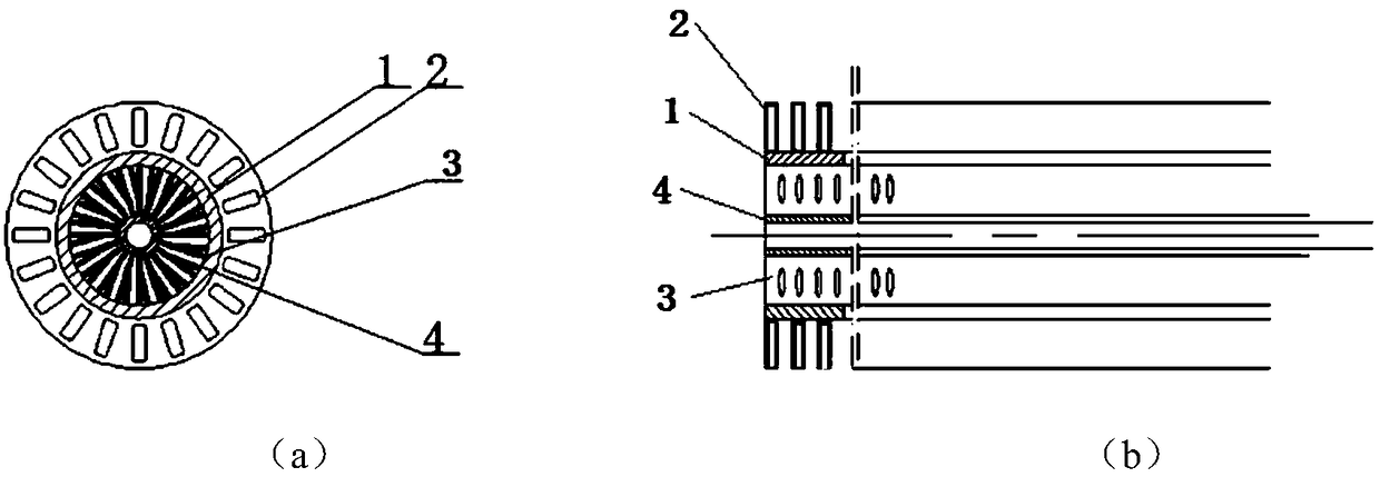
[0055] figure 2 The schematic diagram of the compact gas-gas heat exchange tube provided for this embodiment, the compact gas-gas heat exchange tube includes:

[0056] heat transfer tube 1;

[0057] The outer fin group 2 is arranged on the heat exchange surface outside the heat transfer tube 1 and forms a micro flow channel with an equivalent diameter of 0.5 mm to constrain the fluid outside the tube to flow along the axial direction of the heat transfer tube 1 . Each outer fin of the outer fin group 2 is a metal sheet radially parallel to the heat transfer tube 1, the width of the metal sheet is 1 / 4 of the inner diameter of the heat transfer tube 1, and the thickness is 1mm; each of the outer fin group 2 Each fin has holes. When the fluid outside the tube passes through the outer fins and the holes on the outer fins, it will produce a disturbance effect and enhance convective heat transfer;

[0058] It is arranged on the inner heat exchange surface of the heat transfer tub...

Embodiment 2

[0061] image 3 The schematic diagram of the compact gas-gas heat exchange tube provided for this embodiment, the compact gas-gas heat exchange tube includes:

[0062] heat transfer tube 1;

[0063] The outer fin group 2 is arranged on the outer heat exchange surface of the heat transfer tube 1 and forms a micro flow channel with an equivalent diameter of 0.5 mm to 1 mm to constrain the fluid outside the tube to flow along the axial direction of the heat transfer tube 1 . Each outer fin of the outer fin group 2 is a thin metal strip radially parallel to the heat transfer tube 1, the width of the metal thin band is 1 / 2 of the inner diameter of the heat transfer tube 1, and the thickness is 0.5mm, and the outer fin group 2 Each fin on the tube has a hole. When the fluid outside the tube passes through the outer fin and the holes on the outer fin, it will generate a disturbance effect and enhance convective heat transfer.

[0064] Set on the inner heat exchange surface of the h...

Embodiment 3

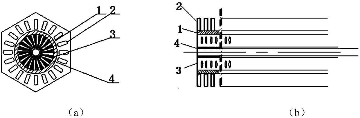
[0067] Figure 4 The schematic diagram of the compact gas-gas heat exchange tube provided for this embodiment, the compact gas-gas heat exchange tube includes:

[0068] heat transfer tube 1;

[0069] The outer fin group 2 is arranged on the outer heat exchange surface of the heat transfer tube 1 and forms a micro flow channel with an equivalent diameter of 2 mm to restrict the fluid outside the tube to flow along the axial direction of the heat transfer tube 1 . Each outer fin of the outer fin group 2 is a metal sheet radially parallel to the heat transfer tube 1, the width of the metal sheet is 1 / 3 of the inner diameter of the heat transfer tube 1, and the thickness is 1.5mm. Each fin has an elliptical hole, and when the fluid outside the tube passes through the outer fin and the holes on the outer fin, it will produce a disturbing effect and enhance convective heat transfer.

[0070] It is arranged on the inner heat exchange surface of the heat transfer tube 1 and forms a ...


PUM


Abstract

The invention provides a compact type gas-gas heat exchange tube which comprises a heat transfer tube, an inner fin set and an outer fin set. The heat transfer tube is used for separating fluid insideand outside the tube and transferring heat between the fluid inside and outside the tube in a convection heat conduction mode; the inner fin set is used for expanding the inside heat exchange surfaceof the heat transfer tube, forming miniature fluid channels, separating the fluid in the tube, making the fluid flow in the axial direction of the heat transfer tube and meanwhile generating a turbulent flow effect and enhancing a convection heat exchange effect; the outer fin set is used for expanding the outside heat exchange surface of the heat transfer tube, forming miniature fluid channels,restraining the fluid outside the tube to reversely flow in the axial direction of the heat transfer tube and meanwhile generating the turbulent flow effect and enhancing the convection heat exchangeeffect; and holes are formed in fins of the inner fin set or/and the outer fin set. The invention further provides manufacturing and use methods of the compact type gas-gas heat exchange tube. Complete reverse flow efficient heat transfer is achieved under the heat exchange working condition of the limited space and the small tube number average temperature difference, the equipment spatial size is reduced, and meanwhile the weight of each area is reduced, so that the total weight and the manufacturing cost are reduced.

Description

technical field [0001] The invention relates to a heat exchange tube for heat transfer, which belongs to the technical field of high-efficiency and compact heat exchangers. Background technique [0002] In recent years, the new power cycle power generation technology has developed rapidly, and cycle power generation systems using helium, hydrogen, carbon dioxide, organic compounds, etc. New application fields such as fourth-generation nuclear power, solar thermal power generation, and ships are being developed based on supercritical carbon dioxide Brayton cycle power generation technology, such as figure 1 shown. The carbon dioxide working medium in the circulation loop is in a supercritical state, and the convective heat transfer characteristics are similar to those of a high-pressure gas-gas heat exchanger. [0003] In all kinds of industrial heat exchangers, heat transfer tubes are the basic heat exchange devices, widely used in shell-and-tube heat exchangers, tube-shee...

Claims


Application Information

Patent Timeline
Patent Type & Authority Applications(China)
IPC IPC(8): F28F1/42
CPCF28F1/42F28F2001/428F28D7/16F28F1/20F28F1/40F28F13/12F28F1/422
Inventor 黄志强郑开云
Owner SHANGHAI POWER EQUIP RES INST
Why Eureka
Try Eureka