A Simulating System and Experimental Method for Synchronous Grouting in Shield Tunneling Method

A technology of synchronous grouting and simulation system, applied in the direction of applying stable tension/pressure to test the strength of materials, instruments, measuring devices, etc., can solve the problems of limited on-site guidance, and achieve the convenience of experimental teaching, reasonable structure design, and pressure value exact effect

Inactive Publication Date: 2020-05-12
SOUTHWEST PETROLEUM UNIV
View PDF7 Cites 0 Cited by
  • Summary
  • Abstract
  • Description
  • Claims
  • Application Information

AI Technical Summary

Problems solved by technology

[0004] The purpose of the present invention is to provide a simulation system and experimental method for synchronous grouting of shield tunneling method in view of the problem of limited on-site guidance in the existing simulated shield tunneling method synchronous grouting experiment

Method used


Image

  • A Simulating System and Experimental Method for Synchronous Grouting in Shield Tunneling Method
  • A Simulating System and Experimental Method for Synchronous Grouting in Shield Tunneling Method
  • A Simulating System and Experimental Method for Synchronous Grouting in Shield Tunneling Method

Examples


Embodiment 1

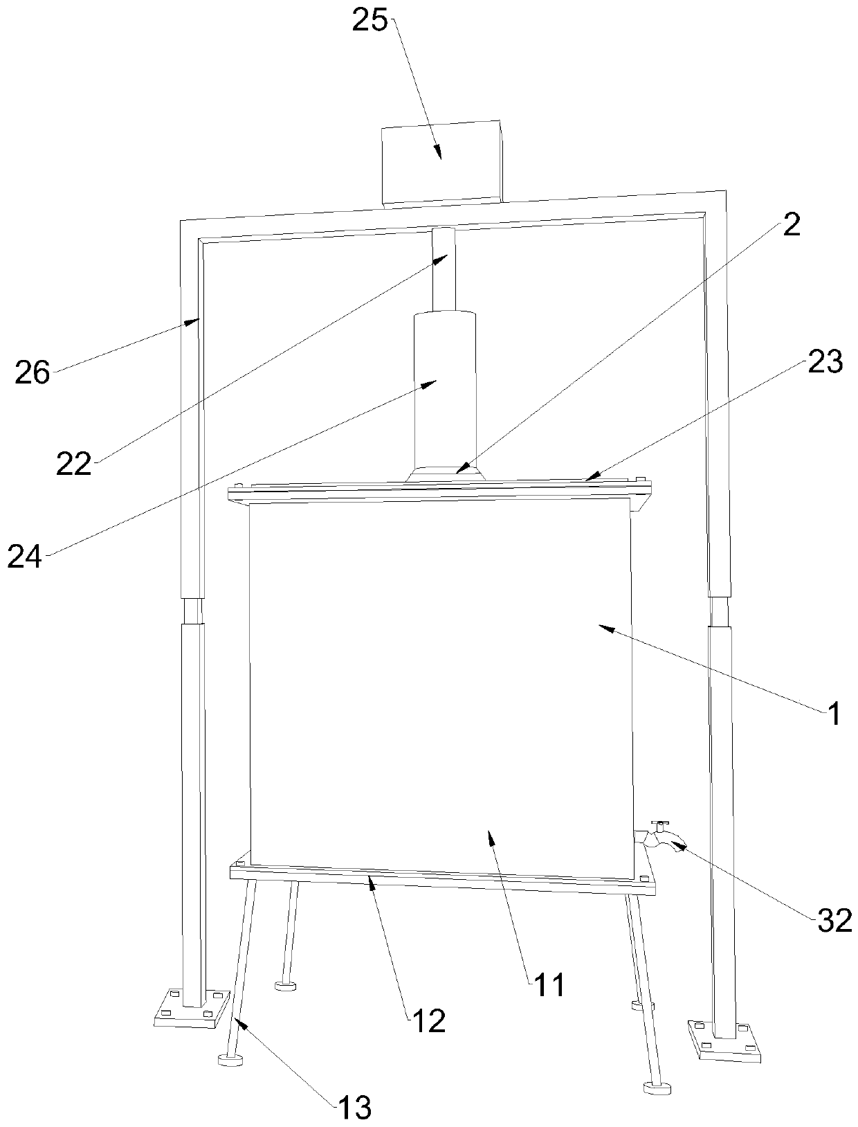
[0036] This embodiment discloses a simulation system for synchronous grouting of shield tunneling method, such as Figure 1-5 As shown, it includes a model device 1 and a propulsion device 2; the model device 1 is a container with an upper end opening; the propulsion device 2 includes a pressurized piston 21, and the pressurized piston 21 is matched with the model device 1; The pressurizing piston 21 and the model device 1 jointly form a closed space for containing the mixed slurry of the experimental soil mass and the synchronous slurry.

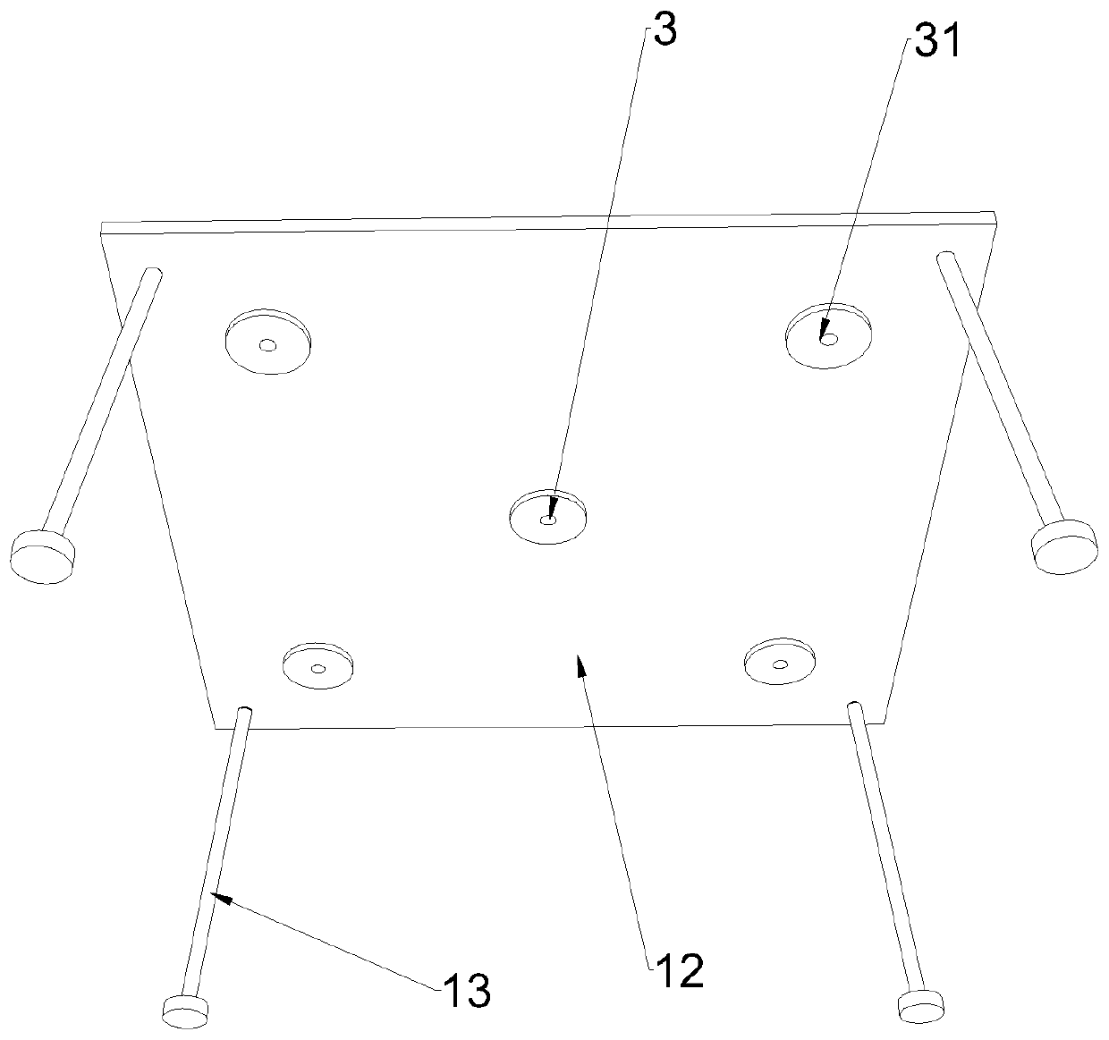
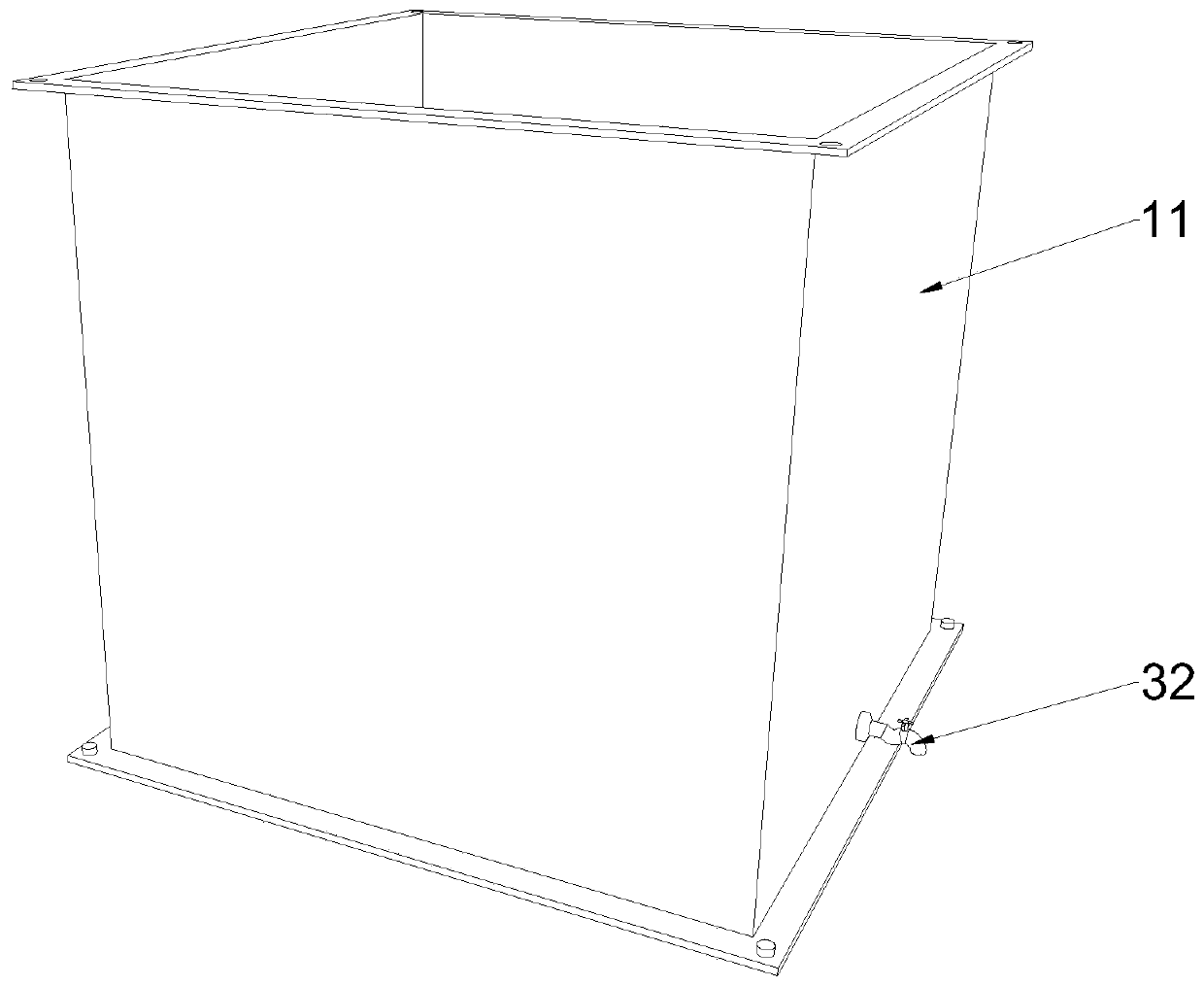
[0037] Specifically, such as Figure 1-5 As shown, the model device 1 includes a sample tube 11 and a bottom plate 12, the sample tube 11 is a container with upper and lower ends open, the bottom plate 12 closes the lower end opening of the sample tube 11, and the bottom plate 12 is detachably connected to the lower end of the sample tube 11 . Base plate 12 is made of steel, and is disassembled and installed through the screw holes at fou...

Embodiment 2

[0060] This embodiment builds on the basis of embodiment 1, such as Image 6 , 7 As shown, the model device 1 also includes an embedded cylinder 14, the embedded cylinder 14 is detachably embedded in the inside of the sample cylinder 11 of the embodiment 1, and the inner space of the embedded cylinder 14 is a cylinder body shape. The pressure piston 21 of Embodiment 1 is also modified accordingly, and changed into a disc shape 27, which together form a closed container with a cylindrical space. The embedded cylinder 14 is made according to the standard size and is made of stainless steel; a water analysis hole needs to be reserved at the position of the water analysis valve so that the cylindrical sample can analyze water smoothly.


PUM


Abstract

The invention belongs to the technical field of shield tunnel engineering simulation experiments, and concretely relates to a simulation system for shield-method synchronous grouting. The simulation system comprises a model device, a propulsion device, a monitoring device and a processing device. The invention also relates to an experimental method for shield-method synchronous grouting. The method comprises the following steps of (1) mixing an experiment soil body and a synchronous slurry to form a mixed slurry; (2) applying pressure on the mixed slurry until the mixed slurry is coagulated toform a test block; (3) acquiring experiment data of surface pressure and coagulation time of the mixed slurry; (4) analyzing the experiment data, and determining parameters of the test block. The invention aims to provide the simulation system and the experimental method for shield-method synchronous grouting aiming at the problem that an existing simulation shield method synchronous grouting experiment is limited in site instruction function. Through a simulated result obtained through the simulation system and the experimental method, a site instruction function is remarkably improved.

Description

technical field [0001] The invention belongs to the technical field of shield tunneling engineering simulation experiments, and in particular relates to a simulation system for synchronous grouting of a shield tunneling method and an experiment method. Background technique [0002] Today, the shield method has been widely used in the construction of urban subways, highways, drainage and other tunnel projects due to its advantages of small disturbance and fast excavation. In the construction of the shield method, as the shield machine advances, a construction gap, that is, the shield tail gap, will be formed between the soil and the segments. In order to control the surface settlement and prevent water leakage from the segments, it is necessary to fill these gaps while the segments are advancing, that is, synchronous grouting. [0003] Synchronous grouting is an important process in the construction of shield tunneling method. Many experts at home and abroad have done a lot ...

Claims


Application Information

Patent Timeline
Patent Type & Authority Patents(China)
IPC IPC(8): G01N3/12
CPCG01N3/12G01N2203/0003G01N2203/0019G01N2203/0048
Inventor 张军伟黄新淼李雪
Owner SOUTHWEST PETROLEUM UNIV
Why Eureka
Try Eureka