
LED image quality enhancing thin film

A technology of LED lamps and films, applied in the field of optical projection, can solve the problems such as the inability to completely eliminate the gap of the display unit, the unclear picture quality of the LED screen, and the uneven color.

Pending Publication Date: 2018-05-01
SHENZHEN HOLOKOOK TECH CO LTD
View PDF0 Cites 0 Cited by
  • Summary
  • Abstract
  • Description
  • Claims
  • Application Information

AI Technical Summary

Problems solved by technology

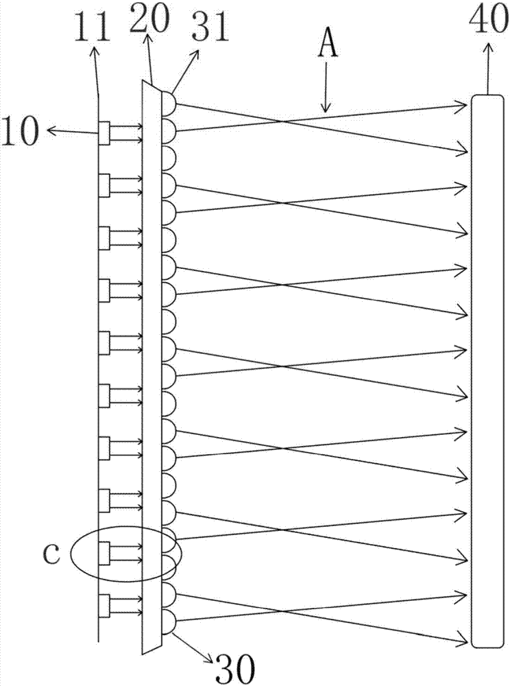
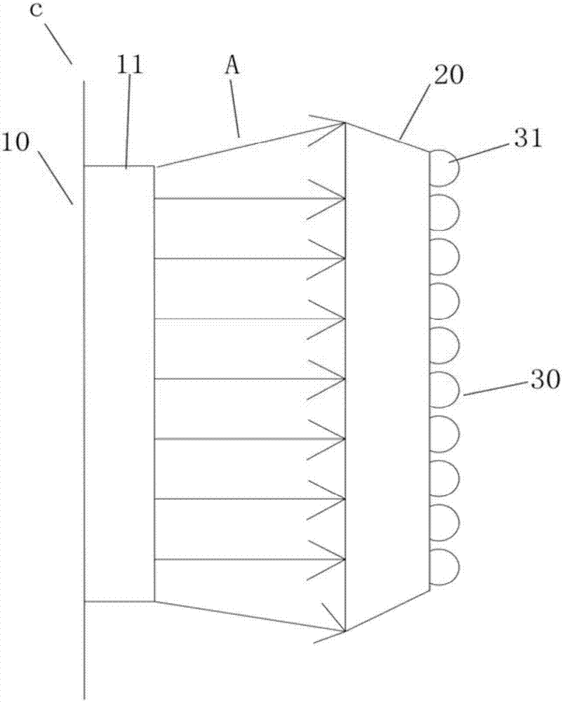
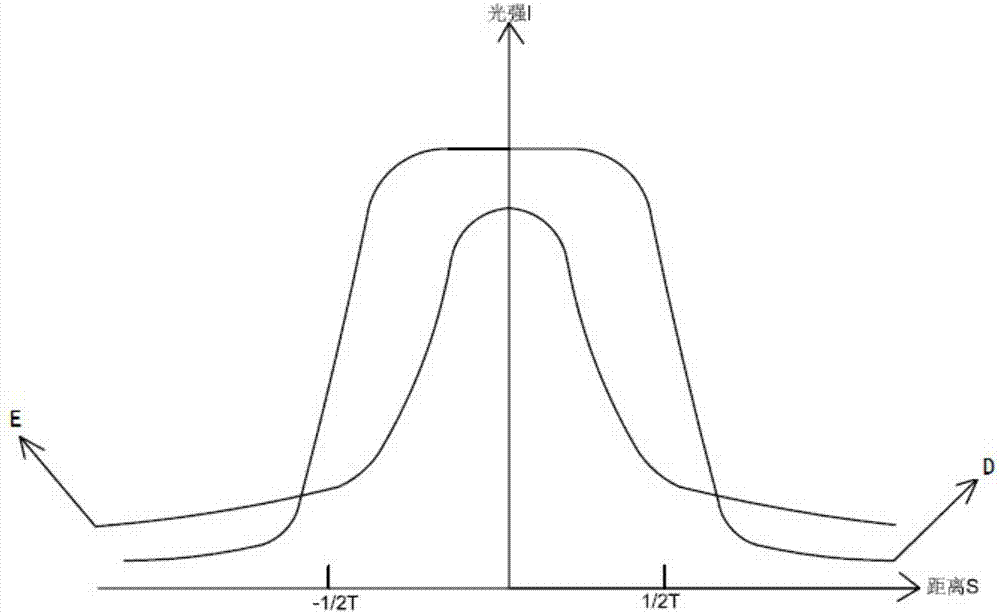
[0003] The invention relates to an LED image quality enhancement film, which is formed by lenses arranged in a certain periodic sequence, and is a film product capable of enhancing the image quality of LED images, which solves the problem of unclear image quality of LED screens and color problems. The problem of uneven distribution and soft enough light can also eliminate the LED stroboscopic effect, increase the color rendering area of ​​the LED screen and realize pseudo-super resolution of pixels. In the field of LED imaging, in many cases, the arrangement of LEDs in the LED display and the The principle of LED screen technology leads to its natural defects, that is, the gap between the display units cannot be completely eliminated, and when viewing the screen at different angles, the color is extremely uneven, and the picture quality is not clear, and the softness of LED light is relatively soft. Poor, and the LED light source has a stroboscopic effect, the LED stroboscopic has a stimulating effect on the human visual system, and will produce uncomfortable feelings. People work or live under the flickering light for a long time, which may also affect the physical health and psychology of the visual system. Hygienic, damage eyesight. For LED screens, the more evenly distributed the luminous points on the screen, the more uniform the luminous light in the same area, and the less fatigue people feel when watching.

Method used


Image

  • LED image quality enhancing thin film
  • LED image quality enhancing thin film
  • LED image quality enhancing thin film

Examples


Embodiment Construction

[0012] The following will clearly and completely describe the technical solutions in the embodiments of the present invention with reference to the accompanying drawings in the embodiments of the present invention. Obviously, the described embodiments are only some, not all, embodiments of the present invention. Based on the embodiments of the present invention, all other embodiments obtained by persons of ordinary skill in the art without making creative efforts belong to the protection scope of the present invention.

[0013] like Figure 1-2 Shown, a kind of LED picture quality enhancing film, this film comprises a substrate 20, and the substrate is a transparent plastic substrate or glass substrate, and the plastic substrate comprises acrylic, polyester, vinyl polymer, and the glass substrate is a general high-transparency Light glass usually has low reflectivity, such as glass with a reflectivity below 1%.

[0014] The base includes upper and lower surfaces, one side of ...


PUM


Abstract

The invention relates to an LED image quality enhancing thin film. The film comprises a substrate, wherein the substrate comprises an upper plane and a lower plane; one or more light guiding layers coats one plane of the substrate; each light guiding layer comprises a plurality of lens particles with particle sizes close to each other; the lens particles comprise light entering surfaces and lightexiting surfaces; the light entering surfaces are straight surfaces which are closely attached to the substrate; the light exiting surfaces are protruded arc surfaces; and a plurality of protruded structures are arranged together according to a periodic sequence to form concave and convex light guiding layer arc surfaces. By the technical scheme, the LED image quality enhancing thin film has the beneficial effects that the developing area of an LED screen is increased, pseudo-super analysis of pixel points is implemented, the softness of light is improved, thus, imaging colors are vivid and bright, and pictures are clear. In addition, the thin film can further eliminate LED stroboscopic effect.

Description

technical field [0001] The invention relates to the field of optical projection, in particular to an LED image quality enhancement film. Background technique [0002] The LED screen is a new type of imaging electronic device made of light-emitting diodes arranged in sequence. Due to its high brightness, wide viewing angle and long life, it is being widely used in outdoor advertising screens and other products. But the picture quality of the existing LED screen is not clear, you can only see it from a distance, you can’t see it up close, the color distribution is uneven, the light is very bright, so the light is not soft enough, and it is very irritating to the eyes when you look at it for a long time. Watching the LED imaging screen from different angles, the screen There are problems of uneven color and brightness distribution, poor light softness, easy to make people feel tired, and the imaging picture is not clear and the resolution is low. In addition, the LED strobosco...

Claims


Application Information

Patent Timeline
IPC IPC(8): G02B3/00G09F9/33
CPCG09F9/33G02B3/0006G02B3/0037
Inventor 郭滨刚屈立军蔡燕青
Owner SHENZHEN HOLOKOOK TECH CO LTD
Learn More