Differential signal generation circuit and electronic system

A differential signal and generation circuit technology, applied in the direction of logic circuit interface device, logic circuit connection/interface arrangement, etc., can solve the problems of poor differential signal quality, influence of data transmission accuracy, etc.

Active Publication Date: 2018-05-01
SEMICON MFG INT (SHANGHAI) CORP +1
View PDF17 Cites 5 Cited by
  • Summary
  • Abstract
  • Description
  • Claims
  • Application Information

AI Technical Summary

Problems solved by technology

[0004] However, the quality of the differential signal generated by the differential signal generating circuit in the prior art is not good, and the waveform of the differential signal generated by it generally has a peak. When the peak is large, it will affect the transmission protocol of the differential signal. The accuracy of data transfers has a serious impact on

Method used


Image

  • Differential signal generation circuit and electronic system
  • Differential signal generation circuit and electronic system
  • Differential signal generation circuit and electronic system

Examples


Embodiment Construction

[0032] As described in the background art section, the quality of the differential signal generated by the differential signal generating circuit in the prior art is poor, which has a serious impact on the accuracy of data transmission in the transmission protocol using the differential signal.

[0033] The inventor of the present application has performed principle analysis and signal simulation on differential signals and a differential signal generating circuit.

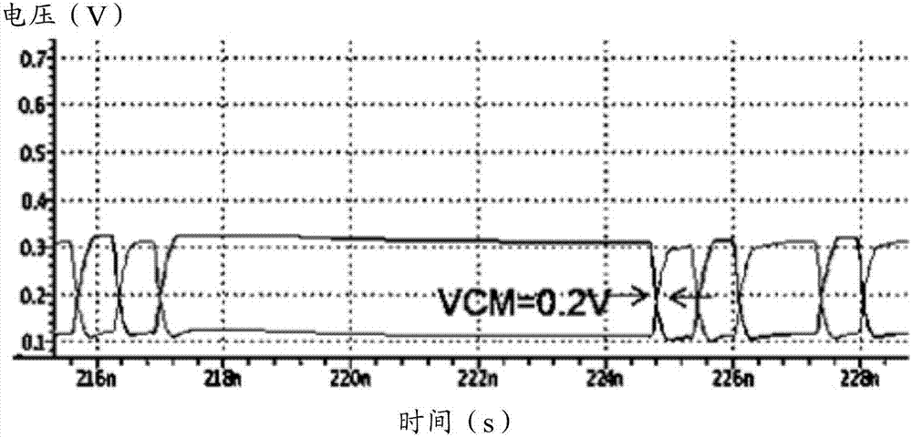
[0034] Since modern high-speed differential signal transmission protocols have certain requirements for differential signals, for example, it may be required, such as MIPI protocol, that both differential mode voltage and common mode voltage of differential signals are 200mV. like figure 1 As shown, the common mode voltage VCM of a pair of differential signals in the figure is about (0.1V+0.3V) / 2=0.2V.

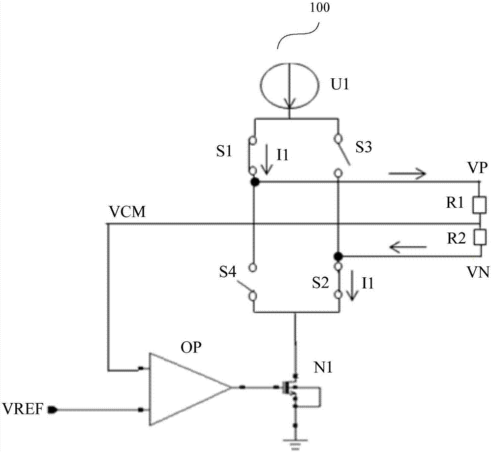
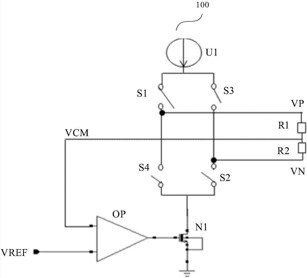
[0035] figure 2 It is a circuit diagram of a differential signal generating circuit. like figure 2 The show...


PUM


Abstract

The invention discloses a differential signal generation circuit and an electronic system. The differential signal generation circuit comprises a differential signal generation unit which generates adifferential positive voltage signal and a differential negative voltage signal under the effect of a control signal and also outputs a common mode voltage signal; an error amplifier unit which is suitable for amplifying the amplitude difference between a first reference voltage signal and the common mode voltage signal; a voltage-controlled current source which is suitable for outputting a pull-down current according to an error voltage output by the error amplifier unit, wherein the pull-down current is used for regulating the amplitude of the common mode voltage signal; a high impedance detection unit which receives a second reference voltage signal and is suitable for pulling up or pulling down the common mode voltage signal when an output end of the differential signal generation unitis in a high impedance state, and is also suitable for comparing the second reference voltage signal with the common mode voltage signal and generating an enabling signal; and a first switch unit ofwhich two ends receive the first reference voltage signal and the common mode voltage signal and is suitable for being switched on or switched off under the effect of the enabling signal. According tothe scheme, the quality of the generated differential signal can be improved.

Description

technical field [0001] The invention relates to the technical field of electronic circuits, in particular to a differential signal generating circuit and an electronic system. Background technique [0002] In the design of high-speed circuits, due to the strong anti-interference ability and the ability to effectively suppress electromagnetic interference, the application of differential signals is gradually widespread. The differential signal is two equal and inverted signals sent by the circuit driving end. The circuit receiving end judges whether the logic state of the differential signal is "0" or "1 by comparing the difference between the two equal and inverted signal voltages. ". In a non-ideal state, the differential signal has a common mode voltage (Common Mode Voltage) due to non-ideal factors such as temperature drift. The common-mode voltage of a pair of differential signals is the average of the amplitudes of the two differential signals. [0003] There are cer...

Claims


Application Information

Patent Timeline
IPC IPC(8): H03K19/0175
CPCH03K19/017509
Inventor 郭振业苏振江
Owner SEMICON MFG INT (SHANGHAI) CORP
Why Eureka
Try Eureka