Remote visible light communication transceiving system

A technology of visible light communication and transceiver system, applied in the field of long-distance visible light communication transceiver system, can solve the problems of complex long-distance environment, noise interference, affecting communication quality, etc., and achieve the effect of reducing communication interference and improving the received signal-to-noise ratio.

Inactive Publication Date: 2018-05-01
DONGGUAN XINDA INST OF INTEGRATED INNOVATION +1
View PDF9 Cites 6 Cited by
  • Summary
  • Abstract
  • Description
  • Claims
  • Application Information

AI Technical Summary

Problems solved by technology

For common long-distance visible light communication systems, there is noise interference in the received information, which affects the quality of communication. How to maximize the received signal energy and minimize noise has always been a problem that needs to be considered. These technical difficulties all affect long-distance visible light communication. Applications
[0003] For the receiving end of long-distance communication, first, the distance between the sending and receiving ends is relatively large. If the receiving end receives the wrong direction, it will not be able to receive the optical signal sent by the transmitting end; The background light signal; the third is that the long-distance atmospheric environment will cause certain interference to the transmitted light signal and make the light signal energy fluctuate randomly

Method used


Image

  • Remote visible light communication transceiving system
  • Remote visible light communication transceiving system
  • Remote visible light communication transceiving system

Examples


Embodiment Construction

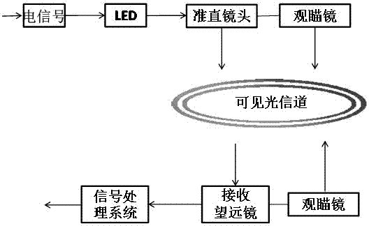
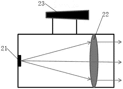
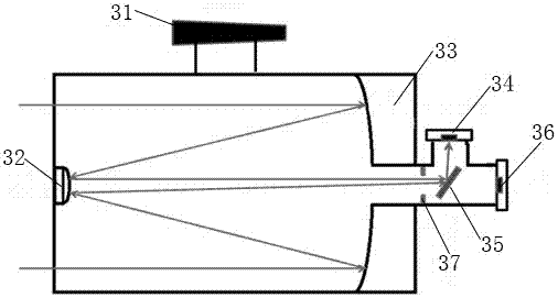
[0021] The present invention provides ideas to solve the problems raised by the above-mentioned background technology: firstly, by placing the LED light source at the focal point of the optical collimator lens, the divergence angle of the light emitted by the light source can be compressed, so that the light energy in the outgoing direction can be more concentrated, At the same time, use the sight glass to adjust the outgoing direction of the light source at the transmitting end so that the receiving end is located at the center of the field of view of the sighting glass, so that the receiving end is in the outgoing direction of the transmitting end; Install a sighting mirror on the device, use this sighting mirror to adjust the receiving direction of the receiving end so that the transmitting end is located in the center of the field of view of the sighting mirror, so as to roughly adjust the receiving direction of the receiving device, and at the same time install an image sen...


PUM


Abstract

The invention relates to the technical field of visible light communication and in particular discloses a remote visible light communication transceiving system. The remote visible light communicationtransceiving system comprises a transmitting device and a receiving device, wherein the transmitting device comprises a sight mirror, an LED light source and a collimation lens; the sight mirror is arranged at the top of the transmitting device; the LED light source and the collimation lens are arranged inside the transmitting device, and the LED light source is arranged at a focal point of the collimation lens; the receiving device comprises the sight mirror, an objective lens and a detection device; the sight mirror is arranged at the top of the receiving device; the objective lens comprises a primary lens and a secondary lens, and the secondary lens is arranged at one end, close to a receiving hole, of the receiving device; the primary lens is arranged at the other end of the receivingdevice, a through hole is formed in the center of the primary lens, the through hole is connected with the detection device, and the detection device is provided with an image sensor, a rotatable retroreflector and a detector. The remote visible light communication transceiving system disclosed by the invention has the advantages that emitted lights are collimated, coarse tuning can be carried out on a visible light communication direction by utilizing the sight mirror, and then fine tuning is carried out by utilizing the image sensor, so that received signal-to-noise ratio is increased, andcommunication interference is reduced.

Description

technical field [0001] The invention relates to the technical field of visible light communication, and specifically discloses a long-distance visible light communication transceiver system. Background technique [0002] In visible light communication, the signal-to-noise ratio of the signal received at the receiving end is one of the important parameters that affect the quality of visible light communication. For common long-distance visible light communication systems, there is noise interference in the received information, which affects the quality of communication. How to maximize the received signal energy and minimize noise has always been a problem that needs to be considered. These technical difficulties all affect long-distance visible light communication. Applications. [0003] For the receiving end of long-distance communication, first, the distance between the sending and receiving ends is relatively large. If the receiving end receives the wrong direction, it ...

Claims


Application Information

Patent Timeline
Patent Type & Authority Applications(China)
IPC IPC(8): H04B10/116
CPCH04B10/116
Inventor 张二峰田忠骏朱义君汪涛郑晓东刘洛琨梁进山王小景
Owner DONGGUAN XINDA INST OF INTEGRATED INNOVATION
Why Eureka
Try Eureka