
Device for optical driver component assembly

A technology of optical drives and components, applied in assembly machines, metal processing equipment, manufacturing tools, etc., can solve the problems of poor quality of optical drive components, difficult operation, laborious operation process, etc., to avoid poor quality, simple operation, easy operation The effect is simple and convenient

Inactive Publication Date: 2018-05-04
徐州市全鑫毛制品有限公司
View PDF5 Cites 2 Cited by
  • Summary
  • Abstract
  • Description
  • Claims
  • Application Information

AI Technical Summary

Problems solved by technology

[0004] The purpose of the present invention is to provide a device for assembling optical drive components to solve the problems of manual assembly of optical drive components, which is difficult to operate, laborious and laborious, and the assembled optical drive components are of poor quality

Method used


Image

  • Device for optical driver component assembly
  • Device for optical driver component assembly

Examples


Embodiment Construction

[0019] The present invention will be described in further detail below by means of specific embodiments:

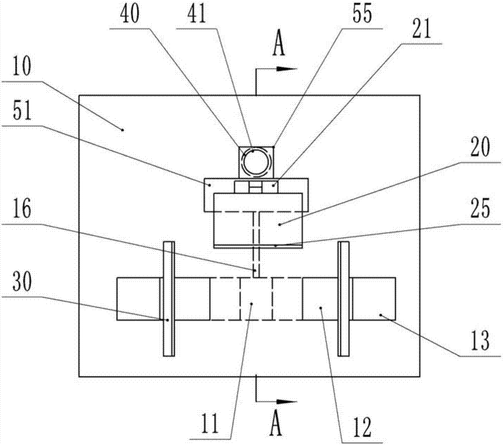
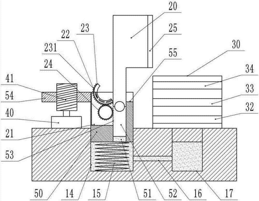
[0020] The reference signs in the drawings of the description include: workbench 10, cavity 11, slider 12, slide cavity 13, column cavity 14, supporting elastic member 15, cavity 16, pressure block 20, concave cavity 21, ring groove 22 , ring block 23, ring gear 231, gear 24, rubber pad 25, clamping frame 30, frame clip 31, optical drive clip 32, floppy drive clip 33, stepper motor 40, threaded rod 41, column block 50, vertical cavity 51, Vertical block 52, rack 53, horizontal block 54, groove 55.

[0021] like figure 1 , figure 2 As shown, the device for assembling the optical drive assembly includes a workbench 10. A cavity 11 is arranged inside the workbench 10. Two ends of the cavity 11 are provided with sliding chambers 13 with openings on the surface of the workbench 10. Inside the two sliding chambers 13 Sliding blocks 12 are respectively arranged in airtight a...


PUM


Abstract

The invention discloses a device for optical driver component assembly. The device comprises a workbench; a cavity is arranged in the workbench; sliding cavities are arranged at the two ends of the cavity respectively and are internally provided with sliding blocks respectively; each sliding block is fixed with a clamping frame; the two clamping frames are oppositely arranged and are provided withframe clamps used for clamping an optical driver frame, optical driver clamps used for clamping an optical driver and floppy drivers used for clamping a floppy driver respectively; the workbench is internally provided with a column cavity and a cavity passage used for communicating the column cavity and a cavity; a column block is connected to the interior of the column cavity in a sliding mannerand is internally provided with a vertical cavity; a vertical block is connected to the interior of the vertical cavity in the sliding manner; a pressure block is hinged to the upper end of the vertical block; a recessed cavity is arranged at the upper end of the column block and is internally provided with a ring groove; the ring groove is internally provided with a ring block in the sliding manner; a gear ring is arranged on the protruded side of the ring block; the recessed cavity is internally provided with a gear which is engaged with the gear ring; and the vertical block is provided with a rack. Compared with the prior art, the device for optical driver component assembly is simple, convenient and rapid in operation process, saves time and labor and can effectively solve the problemof poor quality of the assembled optical driver.

Description

technical field [0001] The invention belongs to the technical field of computer assembly, and specifically discloses a device for assembling an optical drive assembly. Background technique [0002] The optical drive assembly refers to the combination of components mainly including optical drive, floppy drive, hard disk and optical drive bracket or hard disk bracket. These components are assembled together by screws. retract. At present, the optical drive assembly is usually manually assembled. The steps of manual assembly are: first take the optical drive frame and place it on the work table, then take an optical drive and place it on the optical drive frame, and screw all the screw holes on the optical drive frame and the optical drive. It doesn't matter; secondly, take another floppy drive, and screw the screws screwed into the screw holes of the optical drive bracket and the optical drive into the screw holes of the floppy drive, and it is not tight; finally, adjust the ...

Claims


Application Information

Patent Timeline
Patent Type & Authority Applications(China)
IPC IPC(8): B23P21/00
CPCB23P21/00
Inventor 鲁纪忠
Owner 徐州市全鑫毛制品有限公司
Learn More