Welded steel pipes with ribs and method of manufacture

A technology for welding steel pipes and manufacturing methods, applied in the direction of tubular elements, lighting and heating equipment, heat exchange equipment, etc., can solve the problems of inability to adopt processing technology, unfavorable cleaning and cleaning of oil dirt, reduce the range of rib areas, etc., and achieve width and dimension accuracy Easy to control, basically consistent heat transfer efficiency, easy to clean and clean

Inactive Publication Date: 2005-01-26
JONJEE HI TECH INDAL & COMML HLDG +1
View PDF1 Cites 8 Cited by
  • Summary
  • Abstract
  • Description
  • Claims
  • Application Information

AI Technical Summary

Problems solved by technology

Its disadvantages are: (1) The heat conduction efficiency of welded steel pipe is lower than that of copper pipe and aluminum pipe, especially the welded steel pipe with smooth inner wall and the copper pipe with ribs or internal threads on the inner wall, the heat conduction efficiency is lower.
(2) The processing technology of the existing internally threaded copper pipe cannot be used: the internal thread of the internally threaded copper pipe is currently processed by extrusion between the planetary rotary ball on the outside of the pipe wall and the threaded plug fixed on the inside of the pipe The manufacturing process of this method is complicated, and more expensive special equipment must be used. Not only that, but more importantly, the ductility of steel is far inferior to that of copper. In addition, the hardness and shape and size of the weld seam of the welded steel pipe and the inner wall of the pipe in the circumferential direction Inconsistency, thus making it difficult to process welded steel pipe with fins on the inner wall using the above-mentioned process and equipment for processing copper pipe
In this patent, in order to solve the corrugated edge caused by the edge of the plate when the ribs are rolled, the inner wall of the pipe is set along the convex line area of ​​the weld, and all the ribs on the inner wall of the pipe are cut off so that it cannot form a complete thread shape. This brings some other defects that affect the improvement of the heat transfer coefficient of the heat transfer tube: (1) The appearance of the raised area reduces the range of the fin area, so that the heat dissipation area is also reduced accordingly
(2) The wall thickness of the convex strip area is greater than that of the rib area, resulting in uneven wall thickness of the welded pipe and reducing heat transfer performance
(3) All the ribs are terminated in the convex strip area, and form many dead angles, which are easy to accumulate dirt and difficult to clean, so the maintenance is not good
Because during the production or use of the heat transfer tube, mainly during the use process, due to the high discharge temperature of the connected compressor, part of the refrigerated oil will be vaporized, and other impurities and dirt will be bonded to the heat transfer tube. Oil scale is formed on the inner wall of the tube, which increases the thermal resistance and reduces the heat transfer effect. Therefore, after a period of use, the heat transfer effect will decrease, which requires cleaning or cleaning. The dead angle on the inner wall of the tube is very unfavorable for the cleaning of grease. and cleaning
(4) When the heat transfer tube is applied to the evaporator, since the air flow velocity in the evaporator is directly related to the heat transfer efficiency, the higher the speed, the higher the heat transfer efficiency. The fins with complete thread grooves are not conducive to the improvement of air flow velocity, which will affect the further improvement of heat transfer efficiency
(5) The heat transfer tube must use a well-designed special roll mold, and the mold cost is relatively high

Method used


Image

  • Welded steel pipes with ribs and method of manufacture
  • Welded steel pipes with ribs and method of manufacture
  • Welded steel pipes with ribs and method of manufacture

Examples


Embodiment Construction

[0034] The present invention will be further described below in conjunction with the drawings and specific embodiments.

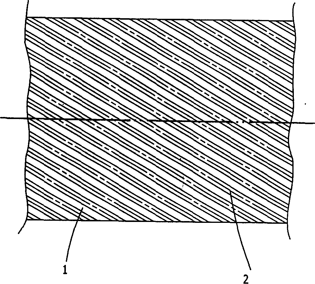
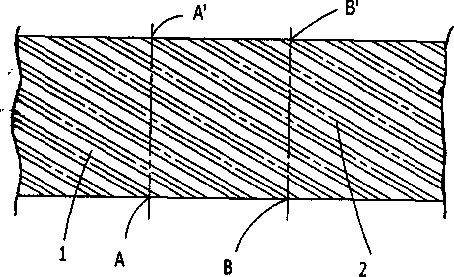
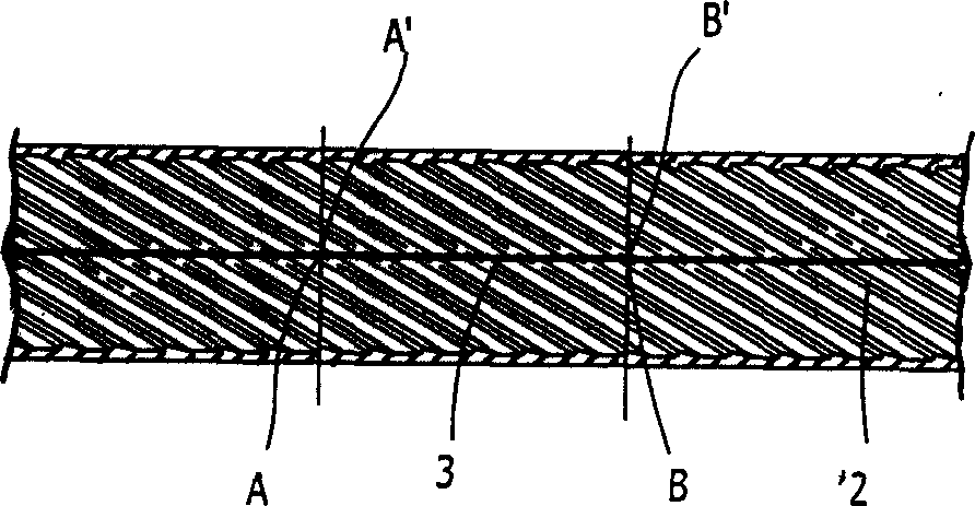
[0035] Figure 1~7 The shown finned welded steel pipe with low cost but improved heat conduction efficiency and its manufacturing method are one of the embodiments of the present invention. The finned welded steel pipe is actually formed on the basis of Bondi pipe It is formed by bending and welding steel strips that have been rolled, sheared and heat-treated. The welding seam is parallel to the longitudinal axis of the steel pipe. There are multiple convex spiral ribs 2 on the wall of the steel pipe 1. These The fins form a certain angle with the longitudinal axis of the steel pipe, that is, the spiral angle, and are parallel and continuously distributed. The cross-sectional shape of the fins is triangular. They are butted with the corresponding fins at the steel pipe welding seam to form a complete spiral rib. Among them, the outer diameter of the steel pipe is...


PUM

PropertyMeasurementUnit
diameteraaaaaaaaaa
heightaaaaaaaaaa

Abstract

The invention relates to a kind of steel tube jointing and making technique with costate pieces, rolling the coiled steel or sheet to make costate pieces, processing the technics such as clipping, intervolving, jointing to make diagonal costate pieces which are parallel to the axes of the steel pipe, with several salience in the inside of the pipe. These costate pieces form angle with the axes of the steel pipe, combined to form consecutive and parallel jointing pipe, it can be made into integrated costate pieces with screw thread. This invention has some advantages such as: having high rate of capability to cost, making costate pieces for jointing with simple measures and without the special and expensive equipments, acquiring jointing steel pipe which has high efficiency but the cost less. The costate pieces inside can be made integrated screw thread, without dead angle, easy to maintain, and easy to clean smeary and wash.

Description

Technical field [0001] The invention relates to a heat transfer metal pipe used in refrigeration and heating systems, in particular to a welded steel pipe with ribs with low cost but improved heat transfer efficiency and a manufacturing method thereof. Background technique [0002] In household appliances, metal pipes are usually used to conduct liquid and air. For example, in air conditioners and refrigerators, metal pipes are used to convey refrigerant. The above-mentioned metal pipes mainly include copper pipes, aluminum pipes, and welded steel pipes. In order to improve the heat transfer coefficient of the heat transfer tube, it is a very effective method to install internal threads or fins on the inner wall of the heat transfer tube, because this can increase the heat transfer area of ​​the inner surface of the heat transfer tube, and at the same time cause the fluid to generate turbulent flow. Avoid laminar flow and reduce the liquid film formed in the tube wall, thereby ef...

Claims


Application Information

Patent Timeline
Patent Type & Authority Applications(China)
IPC IPC(8): F28F1/34
Inventor 叶小舟刘健吴继明
Owner JONJEE HI TECH INDAL & COMML HLDG
Why Eureka
Try Eureka