Unmanned vehicle driving blind area eliminating device and application method thereof

An unmanned vehicle, blind spot technology, applied in signal devices, vehicle parts, transportation and packaging, etc., can solve the problems of blind spot observation, poor operation and control flexibility of inspection equipment, and high energy consumption of equipment operation, so as to improve the accuracy of inspection operations. and reliability, flexibly adjust the operating state, and reduce the energy consumption of equipment operation

Inactive Publication Date: 2018-05-04
CHENGDU YUYA TECH
View PDF8 Cites 4 Cited by
  • Summary
  • Abstract
  • Description
  • Claims
  • Application Information

AI Technical Summary

Problems solved by technology

[0002] During the driving process of the vehicle, there are blind spots for the driver to observe on both sides of the vehicle and within a certain distance from the front of the car. As a result, the driver cannot observe obstacles and pedestrians in the blind spot during the running of the vehicle, which is extremely difficult. It is easy to cause traffic accidents and vehicle damage, which seriously affects the safety of vehicle operation. To solve this problem, the current main method is often to install a number of surveillance cameras evenly distributed around the vehicle to realize 360° observation of the surrounding environment of the vehicle and eliminate The need for blind spots. Although this method meets the needs of eliminating vehicle blind spots to a certain extent, when observing vehicle blind spots, on the one hand, the vehicle needs to be in a specific driving state before blind spot observation can be performed, and continuous observation of blind spots cannot be performed. On the other hand, in the blind spot observation operation, the detection and positioning accuracy of obstacles is poor, and during the operation, the detection equipment cannot be effectively selected and adjusted according to the position of the obstacle, which requires continuous operation of the equipment, which also leads to the failure of the detection equipment. The flexibility of operation and control is poor, and the energy consumption of the equipment is relatively high, which cannot effectively meet the needs of actual use. Therefore, in view of this situation, it is urgent to develop a blind spot elimination device and method for unmanned vehicles to meet the needs of actual use.

Method used


Image

  • Unmanned vehicle driving blind area eliminating device and application method thereof
  • Unmanned vehicle driving blind area eliminating device and application method thereof
  • Unmanned vehicle driving blind area eliminating device and application method thereof

Examples


Embodiment Construction

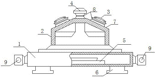
[0019] like figure 1 , 2 As shown in and 3, an unmanned vehicle blind spot elimination device includes a positioning base 1, a detection column 2, a distance measuring device 3, a monitoring camera 4 and a control system 5, and the positioning base 1 is a closed cavity structure with a rectangular cross-section. At least two positioning mechanisms 6 are evenly distributed on the rear surface of the positioning base 1, and are distributed parallel to the lower surface of the vehicle rearview mirror and the horizontal plane through the positioning mechanism 6. The front surface of the positioning base 1 and the detection column 2 are connected to each other and are coaxially distributed. The column 2 is a hollow tubular structure, and its front end surface is evenly distributed with at least four bearing surfaces 7 that are at an angle of 30°-60° with the axis of the detection column 2. There are several distance measuring devices 3, which are evenly distributed around the axis ...


PUM


Abstract

The invention relates to an unmanned vehicle driving blind area eliminating device which comprises a positioning base, a detecting post, ranging devices, a monitoring camera and a control system. Thepositioning base refers to a closed cavity structure with rectangular cross section. The front surface of the positioning base is connected with the detecting device; at least four loading surface areuniformly distributed on the front end face of the detecting device; the ranging devices are arranged on the loading surfaces. The monitoring camera is installed on the front end face of the detecting post through a pan-tilt mechanism. The control system is embedded in the positioning base and in electric connection with the ranging devices, the monitoring camera, the pan-tilt mechanism and an on-board computer respectively. The application method of the device includes two step such as installation of equipment and blind area detection. The unmanned vehicle driving blind area eliminating device has the advantages that the device is easy to control, convenient to install, high in detection and running precision, flexible and convenient to regulate, and further, the device can achieve continuous detection to obstacles according to their locations, regulate running state flexibly and realize reduction of energy consumption.

Description

technical field [0001] The invention relates to a vehicle driving assistance system, which belongs to the technical field of unmanned driving. Background technique [0002] During the driving process of the vehicle, there are blind spots for the driver to observe the positions on both sides of the vehicle and within a certain distance from the front of the car. Therefore, the driver cannot observe the obstacles and pedestrians in the blind spot during the operation of the vehicle. It is easy to cause traffic accidents and vehicle damage, which seriously affects the safety of vehicle operation. In response to this problem, the current main practice is to install several surveillance cameras evenly distributed around the vehicle to realize 360° observation and elimination of the surrounding environment of the vehicle. The need for blind spots, although this method meets the needs of eliminating blind spots of vehicles to a certain extent, but when observing the blind spots of ...

Claims


Application Information

Patent Timeline
Patent Type & Authority Applications(China)
IPC IPC(8): B60Q9/00B60R16/023
CPCB60Q9/008B60R16/0231B60R2300/102B60R2300/802
Inventor 汪梅花
Owner CHENGDU YUYA TECH
Why Eureka
Try Eureka