
Backlash compensation mechanism applicable to reduction mechanism of electric power steering system

A technology of electric power steering and deceleration mechanism, which is applied in the direction of electric steering mechanism, power steering mechanism, steering mechanism, etc. It can solve the problems of affecting driving comfort, worm wheel size change, worm wheel expansion or contraction, etc., to avoid mechanical abnormal noise and The effects of steering destabilization, improving adaptability, and avoiding stuck problems

Active Publication Date: 2018-05-04
WUHU STERLING STEERING SYST
View PDF5 Cites 10 Cited by
  • Summary
  • Abstract
  • Description
  • Claims
  • Application Information

AI Technical Summary

Problems solved by technology

The worm wheel is made of nylon. With the change of ambient temperature and humidity, the worm wheel will expand or contract. After a long time of use, the worm wheel and worm will cause wear and tear, and the size of the worm wheel will change.
The center distance between the meshing center of the worm wheel and the worm and the center distance of the worm wheel hole and the worm hole on the reduction box body will change, resulting in a gap between the worm wheel and the worm or abnormal wear on the tooth surface of the worm wheel, resulting in an increase in the meshing gap between the worm wheel and the worm, and the entire vehicle There will be obvious abnormal noise, which affects the driving comfort
[0005] In addition, the disadvantage of the existing reduction mechanism is that there are manufacturing tolerances and cumulative tolerances. The manufacturing tolerances are mainly due to errors in the machining dimensions of the worm gear and worm, and errors in the machining dimensions of the reduction box. Cumulative formation of center distance and manufacturing tolerances of components such as worm gears and worm gears

Method used


Image

  • Backlash compensation mechanism applicable to reduction mechanism of electric power steering system
  • Backlash compensation mechanism applicable to reduction mechanism of electric power steering system
  • Backlash compensation mechanism applicable to reduction mechanism of electric power steering system

Examples


Embodiment Construction

[0030] The specific embodiment of the present invention will be described in further detail by describing the embodiments below with reference to the accompanying drawings, the purpose is to help those skilled in the art to have a more complete, accurate and in-depth understanding of the concept and technical solutions of the present invention, and contribute to its implementation.

[0031] The deceleration mechanism of the electric power steering system in the prior art has errors in the machining dimensions of the worm gear and worm, and the machining dimensions of the reduction box have errors. The worm gear and worm have wear phenomena, thermal expansion and cold contraction during long-term use, resulting in The meshing center distance of the worm gear and worm and the center distance of the reduction box change, resulting in gaps or abnormal wear on the tooth surface of the worm gear, resulting in an increase in the meshing gap between the worm gear and the worm, and the ...


PUM


Abstract

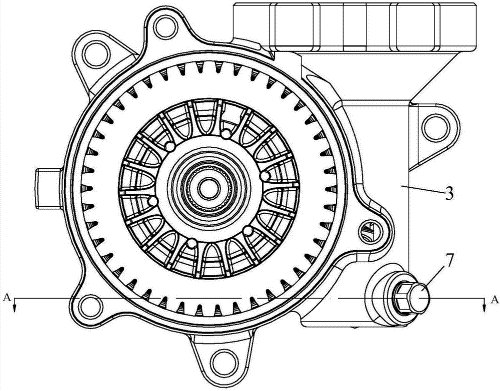
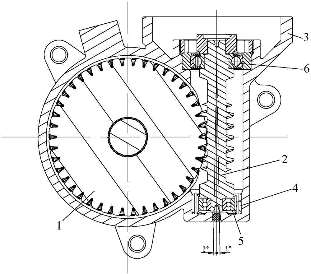
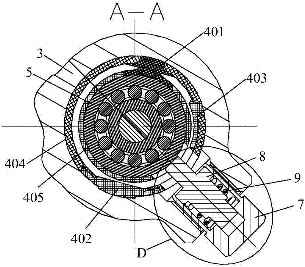
The invention discloses a backlash compensation mechanism applicable to a reduction mechanism of an electric power steering system. The reduction mechanism comprises a reduction box body, a worm gearand a worm, wherein the worm gear is engaged with the worm. The backlash compensation mechanism comprises a first bearing that sleeves the worm, a tolerance compensation ring sleeving the first bearing and allowing the worm to float, and a jackscrew assembly for providing the worm with elastic supporting force. The backlash compensation mechanism has the advantages that jamming or backlash abnormal sound caused by expansion or contraction of the reduction box body, worm gear and worm due to external ambient changes (temperature, humidity and the like) during engaging of the worm gear and the worm, and adaptability of worm-gear engagement is improved; mechanical abnormal sound and steering delay caused by engaging backlash increase due to abrasion of the worm gear and worm can be avoided, and driving comfort is improved.

Description

technical field [0001] The invention belongs to the technical field of electric power steering, and in particular, the invention relates to a gap compensation mechanism suitable for a deceleration mechanism of an electric power steering system. Background technique [0002] Generally, electric power steering is used on most cars. This electric power steering system is based on the ECU controller to control the rotation of the EPS motor according to the changes of the collected sensor torque signal and angle signal. Steering performance. That is, the EPS steering system is used to improve the motion stability of the vehicle by utilizing the power of a separate EPS motor to assist the steering of the vehicle. [0003] Traditionally, hydraulic pressure has been used in auxiliary steering devices, but from the viewpoint of reducing engine load, reducing weight, improving steering stability, and quick return force, recently, the use of a motor suitable for transmitting the rota...

Claims


Application Information

Patent Timeline
Patent Type & Authority Applications(China)
IPC IPC(8): B62D5/04F16H57/022F16H57/12
CPCB62D5/0454F16H57/022F16H2057/02082F16H2057/0213F16H2057/0222F16H2057/0225F16H2057/126
Inventor 刘智斌倪申敏潘伟吴香进陈庆汪明周凡杨建超马威高欣胡玉梅齐一鸣周道洋
Owner WUHU STERLING STEERING SYST
Learn More