Strip rewinding system

A strip and slitting technology, which is applied in the direction of winding strips, thin material processing, and sending objects, can solve the problems of limited diameter, leaving traces at the joints, and reducing work efficiency, so as to achieve stable force and increase The effect of increasing the diameter and length of the aluminum coil

Active Publication Date: 2019-05-31
CHONGQING DONG CHONG ALUMINUM CO LTD
View PDF6 Cites 1 Cited by
  • Summary
  • Abstract
  • Description
  • Claims
  • Application Information

AI Technical Summary

Problems solved by technology

[0004] In addition, in the actual application of aluminum strips, it is often necessary to apply longer aluminum strips. Since the diameter of the aluminum coils wound from the aluminum strips is limited, the length of the aluminum strips of a single aluminum coil cannot meet the application requirements; During the process, multiple aluminum strips need to be connected to meet the length requirement
Connecting aluminum strips will reduce work efficiency on the one hand, and on the other hand, the connected aluminum strips will leave traces at the joints, so sometimes the application requirements cannot be met

Method used


Image

  • Strip rewinding system
  • Strip rewinding system
  • Strip rewinding system

Examples


Embodiment 1

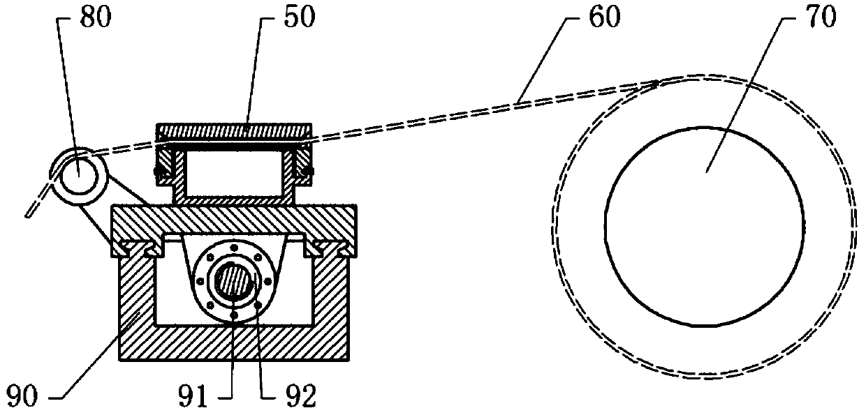
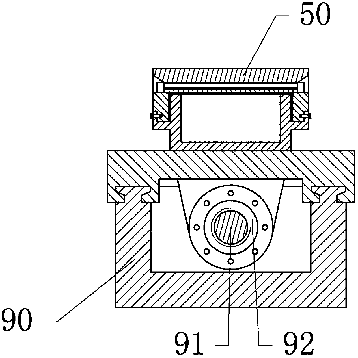
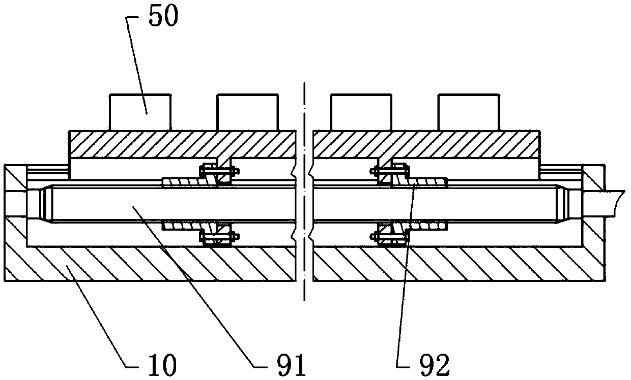
[0031] The strip slitting and rewinding system of this embodiment includes a frame, a winding shaft 70, a drive motor, a strip tensioning device 90 and a PLC controller; the winding shaft 70 is rotatably connected to the frame, and the drive motor can drive the winding shaft 70 Rotate. The strip tensioning device 90 includes a base 10, a servo motor, a reciprocating shaft, a partition plate 80 and a reciprocating mechanism; figure 1 As shown, the base 10 is provided with two parallel slide rails, and the reciprocating shaft is slidably connected to the two slide rails, so that the reciprocating shaft can only slide along the slide rails, and the axial directions of the reciprocating shaft and the winding shaft 70 are mutually opposite. Parallel, that is, the direction in which the reciprocating shaft reciprocates is parallel to the center of rotation of the winding shaft 70. The partition disk 80 is fixed on the reciprocating shaft, and the reciprocating shaft is located betwee...

Embodiment 2

[0041] The difference between the first embodiment and the second embodiment is that the reciprocating mechanism is different. The reciprocating mechanism of the second embodiment includes a gear rotatably connected to the base and a rack fixed on the reciprocating shaft, the rack is located between the two rails, and the gear meshes with the rack. The output shaft of the servo motor is connected with the gear spline, so that during the continuous forward and reverse rotation of the servo motor, the gear will be driven forward and reverse continuously, and the rack will drive the reciprocating shaft to slide back and forth on the track.


PUM


Abstract

The invention discloses a strip splitting and re-winding system, and relates to metal belt winding devices. The system comprises a rack, a winding shaft, a drive motor for driving the winding shaft torotate, a PLC and a strip tensioning reciprocating device; the strip tensioning reciprocating device comprises a base, a servo motor, a reciprocating shaft and a reciprocating mechanism, the base isfixed to the rack, the reciprocating shaft is in sliding connection with the base, the servo motor is connected with the reciprocating shaft through the reciprocating mechanism, and can drive the reciprocating shaft to do reciprocating sliding on the base, multiple tensioning parts are arranged on the reciprocating shaft, each tensioning part comprises a first pressing block, a second pressing block, and a pressure source fixed to the reciprocating shaft, the first pressing block and the second pressing block are opposite, the first pressing blocks and the reciprocating shaft are fixed, the pressure sources can drive the second pressing block to move towards the first pressing blocks, flexible layers are arranged on the opposite side faces of the first pressing blocks and the second pressing blocks, and the drive motor and the servo motor are both electrically connected with the PLC. According to the system, multiple aluminum strips can be re-wound at the same time, the aluminum roll diameter can be increased, and the aluminum strip length can be increased.

Description

Technical field [0001] The invention relates to a metal belt winding device, in particular to a strip slitting and rewinding system. Background technique [0002] Aluminum strip is a strip obtained by pressing and rolling aluminum ingots. Aluminum strip has many uses. It can be used to produce aluminum-plastic composite pipes, cables, optical cables, transformers, heaters, shutters, etc. In order to facilitate the transportation and storage of aluminum strips, the aluminum strips are usually wound into rolls; in addition, according to different needs and uses, it is usually necessary to cut the wider aluminum strips into aluminum strips that fit the width through a slitting machine. Then, the slit aluminum tape is wound into a roll. [0003] Aluminum strips usually have different widths and thicknesses according to different needs and uses. When winding aluminum strips, aluminum strips of different thicknesses and widths can withstand different tensions. As the thickness and wid...

Claims


Application Information

Patent Timeline
Patent Type & Authority Patents(China)
IPC IPC(8): B65H18/08B65H23/198B65H23/10B65H35/02
CPCB65H18/08B65H23/105B65H23/1955B65H23/198B65H35/02B65H2701/1732
Inventor 不公告发明人
Owner CHONGQING DONG CHONG ALUMINUM CO LTD
Why Eureka
Try Eureka