A gas diversion and confluence device

A gas diversion and confluence valve technology, which is applied in the direction of electrical components, gaseous chemical plating, semiconductor/solid-state device manufacturing, etc., can solve the problems of gas residue, complex and simple gas path, and achieve the effect of preventing condensation

Active Publication Date: 2020-04-24
PIOTECH CO LTD
View PDF7 Cites 0 Cited by
  • Summary
  • Abstract
  • Description
  • Claims
  • Application Information

AI Technical Summary

Problems solved by technology

The function of the existing single V-block valve is relatively simple, and the internal gas path of the valve body is complicated. When the valve body is purged and pumped, it is easy to form a dead angle inside the valve body, causing the gas to remain inside the valve body. Therefore, it is necessary to design a new type of gas The diversion and confluence device meets the requirements of use

Method used


Image

  • A gas diversion and confluence device
  • A gas diversion and confluence device
  • A gas diversion and confluence device

Examples


Embodiment Construction

[0022] In order to make the object, technical solution and advantages of the present invention clearer, the present invention will be further described in detail below in conjunction with the accompanying drawings and embodiments. It should be understood that the specific embodiments described here are only used to explain the present invention, not to limit the present invention.

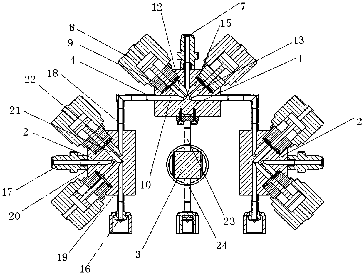
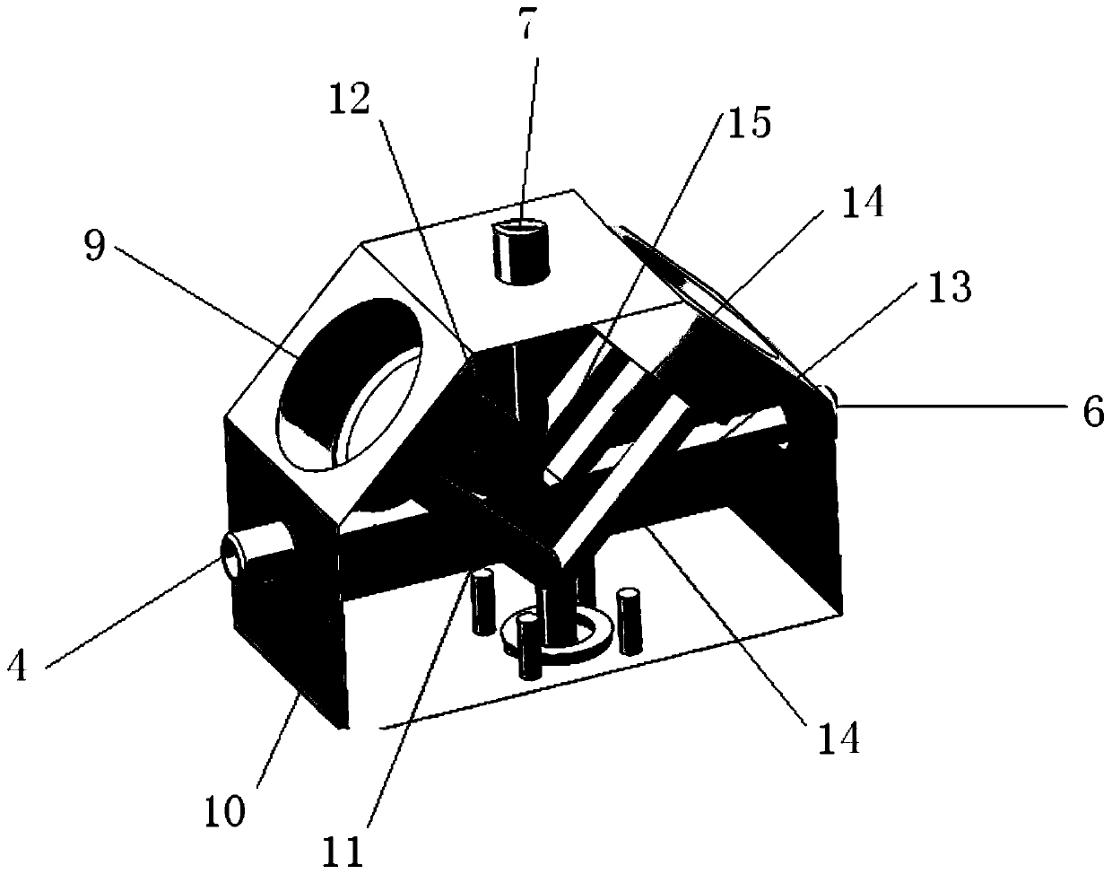
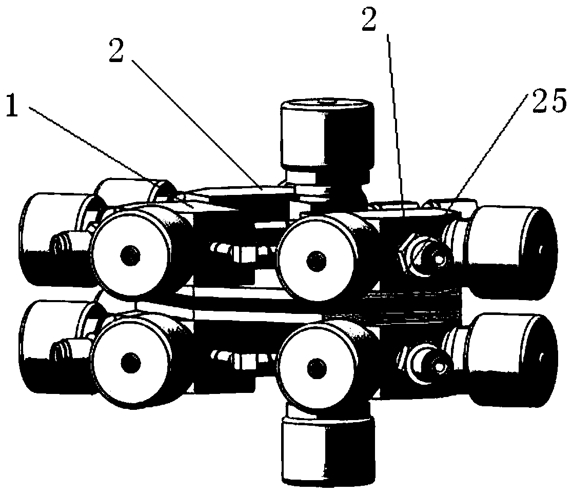
[0023] refer to Figure 1-2 , the present invention provides a gas diversion and confluence device, which is used in semiconductor coating deposition equipment, including a confluence valve 1, a steering valve diversion valve 2 and a purge valve 3. The confluence valve 1 is provided with a plurality of air inlets and One air outlet, the one air inlet is connected to a purge valve 3, and the other air inlets are connected to a diverter valve 2 respectively.

[0024] The confluence valve 1, the diversion valve 2 and the purge valve 3 are all provided with a plurality of mutually independent air inle...


PUM


Abstract

The invention relates to the technical field of semiconductor film deposition equipment, in particular to a gas flow separation and gathering device capable of introducing multiple process gas. The gas flow separation and gathering device comprises a flow gathering valve, flow separation valves and a cleaning valve; the flow gathering valve is provided with multiple intake ports and an exhaust port; one intake port is connected with the cleaning valve; and the rest intake ports are correspondingly connected with the flow separation valves. Intake and exhaust pipes, independent from each other,are arranged in the flow gathering valve, the flow separation valves and the cleaning valve. The gas flow separation and gathering device has the following advantages: the flow gathering valve, the flow separation valves and the cleaning valve are integrated, and meanwhile, realizes flow separation of process gas; the valves use direct welding for replacing VCR to obtain the shortest connecting distance to reduce the shortest gas stop time and stop space in valve bodies; and meanwhile, the device is provided with a heating substrate for effectively preventing condensation of liquid-state source gas in the valve bodies and pipelines.

Description

technical field [0001] The invention relates to the technical field of semiconductor thin film deposition equipment, in particular to a gas splitting and merging device capable of feeding various process gases. Background technique [0002] During the semiconductor coating process, a variety of special gases entering the cavity will be divided, merged, mixed and discharged. In different process stages, in order to avoid the reaction of various gases in the valve body to produce Particles (impurity particles) , the valve body needs to be purged and exhausted several times. The function of the existing single V-block valve is relatively simple, and the internal gas path of the valve body is complicated. When the valve body is purged and pumped, it is easy to form a dead angle inside the valve body, causing the gas to remain inside the valve body. Therefore, it is necessary to design a new type of gas The diversion and confluence device meets the requirements of use. Content...

Claims


Application Information

Patent Timeline
Patent Type & Authority Patents(China)
IPC IPC(8): C23C16/44C23C16/455H01L21/67
CPCC23C16/4401C23C16/455H01L21/67017
Inventor 周仁张宝戈孙泽江徐建
Owner PIOTECH CO LTD
Why Eureka
Try Eureka