Novel thermal insulating wall connecting unit

A technology for thermal insulation walls and connectors, applied in thermal insulation, building components, buildings, etc., can solve the problems of low shear strength, low construction efficiency, complex layout, etc., to increase the friction coefficient, save work time, and improve work efficiency. Effect

Active Publication Date: 2018-05-04
ANHUI UNIVERSITY OF ARCHITECTURE
View PDF6 Cites 7 Cited by
  • Summary
  • Abstract
  • Description
  • Claims
  • Application Information

AI Technical Summary

Problems solved by technology

Foreign sandwich insulation walls generally use rod-shaped and lattice-type connectors. my country's sandwich insulation walls generally use sheet-shaped connectors. There are some shortcomings in various types of connectors, which are specifically manifested in: 1. Low shear strength, Narrow application range, such as rod-shaped connectors; this connector is a non-shear connector, which does not transmit or only partially transmits the shear force between the inner wall and the outer concrete slab, so it can only be used in the enclosure wall, Not for use in load-bearing walls
2. The installation is inconvenient and the layout is more complicated, such as sheet connectors; the sheet connectors are composed of a sheet connector and a sheet collar set on the connector, and the sheet connector and the sheet collar The moment of inertia in different directions of the cross-section is different (there are strong and weak axes), the bending performance of the two directions of the cross-section is significantly different, and the bending performance of the weak axis is poor. There is a great influence on the mechanical performance of the ring, which makes it difficult to arrange the sheet connectors of the wall with different mechanical characteristics, so the layout and installation are complicated and inconvenient
3. The anchoring performance is poor, the production process is complicated, and the construction efficiency is low, such as lattice connectors

Method used


Image

  • Novel thermal insulating wall connecting unit
  • Novel thermal insulating wall connecting unit
  • Novel thermal insulating wall connecting unit

Examples


Embodiment Construction

[0023] Referring to the accompanying drawings, the present invention will be further described in detail below in conjunction with specific embodiments, which are explanations rather than limitations of the present invention.

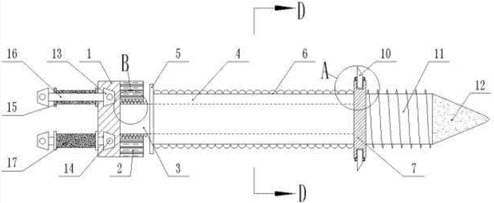
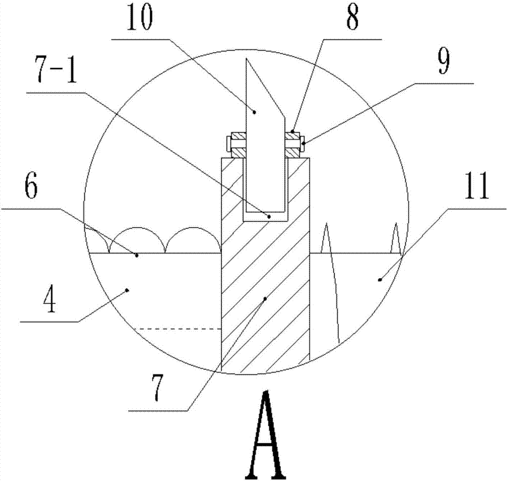
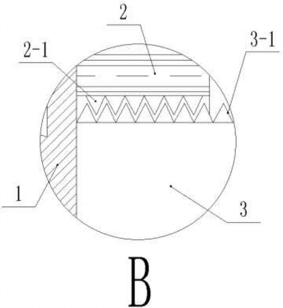
[0024] As shown in the drawings, a new type of thermal insulation wall connector includes a positioning block 1 and a connecting rod 3 arranged on one side of the positioning block 1; one end of the positioning block 1 is fixed with a first sleeve 2, and the first A sleeve 2 is fixed with an internal thread 2-1, one end of the connecting rod 3 close to the positioning block 1 is fixed with an external thread 3-1, and the other end of the connecting rod 3 is inserted into the plastic collar 4, and the internal thread 2-1 is matched with the external thread 3-1, the section of the plastic collar 4 is a circular section, the connecting rod 3 and the plastic collar 4 adopt an interference fit, and the plastic collar 4 is close to the outside of the connectin...


PUM


Abstract

The invention relates to a novel thermal insulating wall connecting unit. The novel thermal insulating wall connecting unit comprises a locating block and a connecting rod arranged on one side of thelocating block, wherein a first sleeve is fixedly arranged at one end of the locating block; the connecting rod is inserted into a plastic lantern ring with a round section; the connecting rod and theplastic lantern ring are in interference fit; a locating ring is fixedly arranged at the end, close to the external thread of the connecting rod, of the plastic lantern ring, and a rib ring is fixedly connected at the other end of the plastic lantern ring; slide grooves are formed in upper and lower sides of the rib ring, and openings of the slide grooves face outwards and are perpendicular to the axis of the plastic lantern ring; a second sleeve is fixedly arranged on the outer side of each slide groove, a locking bolt is in threaded connection onto the second sleeve, and central axis of thesecond sleeve and central axis of the slide groove are located on the same vertical axis; a trapezoidal plate is connected in each second sleeve, and the bottom end of the trapezoidal plate extends into the corresponding slide groove and in sliding connection in the slide groove; a threaded rod is fixedly connected at the outer end of the rib ring, and a conical head is fixed at the outer end ofthe threaded rod.

Description

technical field [0001] The invention belongs to the field of civil engineering and relates to a connector, in particular to a novel thermal insulation wall connector. Background technique [0002] Studies have shown that the energy consumption caused by the building envelope system (external wall) accounts for more than 80% of the building energy consumption. Improving the energy-saving level of the building envelope system is an important measure to reduce building energy consumption. The energy-saving thermal insulation structure of building exterior walls can be mainly divided into three categories, namely: external thermal insulation, internal thermal insulation and sandwich thermal insulation. External thermal insulation is an energy-saving structure formed by placing thermal insulation materials on the outside of the outer wall. This structure has disadvantages such as large impact by the environment, poor durability, and easy fall-off of thermal insulation materials....

Claims


Application Information

Patent Timeline
Patent Type & Authority Applications(China)
IPC IPC(8): E04B1/38E04B1/41E04B1/48E04B1/76E04C2/288
CPCE04B1/38E04B1/4121E04B1/4157E04B1/483E04B1/7629E04C2/2885
Inventor 丁克伟陈东马巍彭健雄
Owner ANHUI UNIVERSITY OF ARCHITECTURE
Why Eureka
Try Eureka