
Method of improving heat exchanging efficiency after fracturing of dry hot rock

A heat transfer efficiency, hot dry rock technology, applied in the direction of earthwork drilling, wellbore/well components, production fluids, etc., can solve the problem that hydraulic fracturing is difficult to completely control the distribution and number of fractures, and the structure of underground rock mass is complex and difficult. Form heat exchange paths and other issues to achieve the effects of reducing development costs, promoting heat exchange, and improving circulation paths

Active Publication Date: 2018-05-04
青海九零六工程勘察设计院有限责任公司 +1
View PDF7 Cites 10 Cited by
  • Summary
  • Abstract
  • Description
  • Claims
  • Application Information

AI Technical Summary

Problems solved by technology

[0004] However, due to the complex structure of underground rock mass and the lack of practical monitoring methods, it is often difficult to fully control the distribution and number of fractures in hydraulic fracturing.
In the area near the wellbore of hydraulic fracturing, dense fractures are usually formed, and too many fractures will cause the loss of heat-carrying fluid, making it difficult to form an effective heat transfer path, resulting in low heat transfer efficiency

Method used


Image

  • Method of improving heat exchanging efficiency after fracturing of dry hot rock

Examples


Embodiment Construction

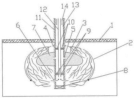
[0028] see figure 1 As shown, a method for improving heat exchange efficiency after hot dry rock fracturing includes the following steps:

[0029] 1. Select the hot dry rock reservoir 2, use drilling equipment to drill through the hot dry rock caprock 1, and drill to the bottom area of ​​the hot dry rock reservoir 2;

[0030] 2. After lifting out the drilling tool, run the production casing 13 and the bottom hole packer 8 with a thermal conductivity greater than 90W / (m·K) along the drilling trajectory, and use a high-temperature heat-resistant thermal conductivity greater than 8W / (m·K) Cement 7 cementing;

[0031] 3. Lower the perforating equipment into the hot dry rock fracturing target reservoir, shoot through the production casing 13, the cement sheath 11 and the hot dry rock reservoir 2 to form the hot dry rock fracturing holes 5, and the hot dry rock fracturing According to actual engineering needs, 2-4 holes are evenly arranged in the circumferential direction, and 1-3...


PUM

PropertyMeasurementUnit
Thermal conductivityaaaaaaaaaa

Abstract

The invention discloses a method of improving the heat exchanging efficiency after fracturing of dry hot rock, and belongs to the field of geothermal energy development. According to the method, a single well fracturing technology is used; high temperature resistant heat-conducting cement is poured into the hydraulic fracturing position of dry hot rock reservoirs, so that sheeted fissure in the hydraulic fracturing near-well area are closed, and only fissure in the far-well area are reserved. The purposes of improving the flowing path of heat carrying fluid and improving the heat exchanging efficiency are achieved. Distribution and arrangement of upper circulating holes and lower circulating holes can enlarge the flowing area of the heat carrying fluid to a maximum extent, and promote heatexchanging of the heat carrying fluid and the dry hot rock reservoirs. Under the action of ground suction force, the heat carrying fluid passes through the upper circulating holes, fissures producedby fracturing, the lower circulating holes and heat insulation oil pipes and then returns to the ground, in this way, the heat exchanging efficiency after fracturing of the dry hot rock can also be improved. Though application of the single well technology and the method of improving the heat exchanging efficiency after fracturing of the dry hot rock, the dry hot rock development cost can be reduced, environmental destruction can be reduced, and the single well fracturing technology and the method of improving the heat exchanging efficiency after fracturing of the dry hot rock play a positiverole in widespread use of geothermal energy.

Description

technical field [0001] The invention relates to the field of geothermal energy development, in particular to a method for improving heat exchange efficiency after hot dry rock fracturing. Background technique [0002] Under the background of global energy consumption gradually becoming clean and renewable, geothermal energy has become a popular new energy source. Geothermal energy is widely distributed and easy to develop and utilize. It is an excellent renewable energy source and has a good utilization prospect. Hot dry rock is a hot rock mass without water or steam that exists deep in the formation. It is generally buried 3-10km below the surface and has a temperature range of 150-650°C. It is an important part of geothermal energy resources. [0003] The method of obtaining thermal energy in hot dry rock is usually called enhanced geothermal system, which is an engineering technology to extract economically valuable geothermal resources from hot dry rock through deep dri...

Claims


Application Information

Patent Timeline
IPC IPC(8): E21B43/26E21B33/13E21B33/122
CPCE21B33/122E21B33/13E21B43/26
Inventor 许伟林罗银飞雷玉德王万平
Owner 青海九零六工程勘察设计院有限责任公司
Learn More