
An Energy Saving Sequence Valve

A sequential valve, energy-saving technology, applied in the field of hydraulic valve manufacturing, can solve problems such as energy loss, achieve the effect of reducing pressure loss and reasonable structure

Active Publication Date: 2020-12-08
TAIZHOU QIHANG MOTOR
View PDF8 Cites 0 Cited by
  • Summary
  • Abstract
  • Description
  • Claims
  • Application Information

AI Technical Summary

Problems solved by technology

The current sequence valves on the market rely on the inlet pressure to be maintained above the set pressure to ensure the connection between the inlet and the outlet. Once the pressure is lower than the set pressure, the sequence valve will close the valve port; in actual application requirements, Mostly, after one actuator is in place, the system pressure rises to the set pressure of the sequence valve and the sequence valve is opened to connect to another oil circuit, but the pressure demand of the other oil circuit is not high, so there is a problem between the inlet and outlet of the sequence valve. Large pressure drop, hydraulic energy is converted into heat energy, resulting in energy loss

Method used


Image

  • An Energy Saving Sequence Valve
  • An Energy Saving Sequence Valve

Examples


Embodiment Construction

[0020] The present invention will be further described in detail below in conjunction with the accompanying drawings and embodiments.

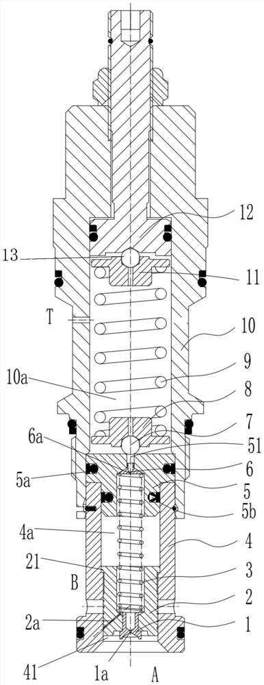
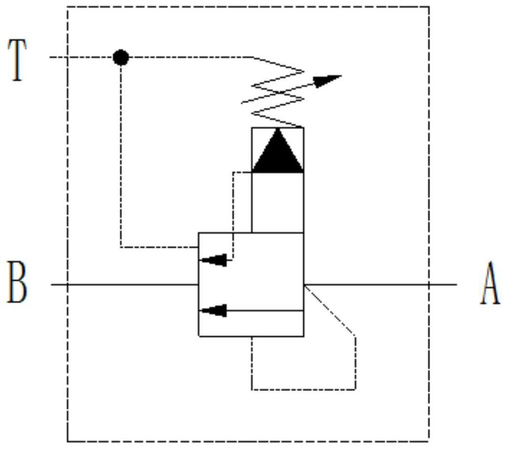
[0021] Such as figure 1 Shown is the structural representation of the present invention,

[0022] An energy-saving sequence valve, comprising a valve body 10, which has an axial through hole, and a T port is opened on the side wall of the valve body 10; a valve sleeve 4, which has an axial through hole, and the valve sleeve 4 is clamped on the valve body In the lower port of 10, the lower port of the valve sleeve 4 forms the A port, and there is a B port on the wall of the valve sleeve 4, and a flow valve port connecting the A port and the B port is formed in the valve sleeve 4; the main valve core 2 is set In the valve sleeve 4 and can slide up and down, the outer peripheral surface of the main valve core 2 cooperates with the through-flow valve port 41, so that the up-and-down sliding of the main valve core 2 can open and close the through-...


PUM


Abstract

The invention discloses an energy-saving sequence valve, which comprises a valve body with an axial through hole, a valve pocket with an axial through hole, a main valve core, a pilot valve seat, a pilot valve core and a pressure setting component, wherein the valve body is provided with a port T; the valve pocket is provided with a port A and a port B; the main valve core is arranged in the valvepocket and can slide up and down; a peripheral surface of the main valve core cooperates with a through-flow valve port, and can open and close the through-flow valve port; the upper part of the pilot valve seat is arranged in the valve body; the lower part of the pilot valve seat is inserted into the valve pocket; a first spring is arranged between the pilot valve seat and the main valve core ina supporting manner; a control cavity is formed between the pilot valve seat and the main valve core; an oil returning cavity is formed between the pilot valve seat and the valve body; a third damping hole, one end of which is communicated with the control cavity, is arranged in the main valve core; the other end of the third damping hole is upwards slid in the main valve core to be capable of being communicated with the port B when communicating the port A with the port B; the pilot valve core is located in the oil returning cavity, and can control the connection and the disconnection, withthe oil returning cavity of a first through-flow hole; the pressure setting component is located at the upper part of the pilot valve core; the pressure setting component is used for setting opening pressure of the pilot valve core. The energy-saving sequence valve has advantages of having a reasonable and compact structure, needing not to keep the port A under set pressure after the main valve core is opened and having an energy saving effect.

Description

technical field [0001] The invention relates to the technical field of hydraulic valve manufacturing, in particular to an energy-saving sequence valve. Background technique [0002] Sequence valve is a kind of pressure control valve. Its main function is to use pressure as the control signal to automatically connect or cut off a certain oil circuit under a certain control pressure. The sequence valve is equivalent to a hydraulic switch, and the high-pressure oil at the outlet will do work when it is connected to the load, so the pressure loss when the liquid flows through the valve port should be as small as possible. The current sequence valves on the market rely on the inlet pressure to be maintained above the set pressure to ensure the connection between the inlet and the outlet. Once the pressure is lower than the set pressure, the sequence valve will close the valve port; in actual application requirements, Mostly, after one actuator is in place, the system pressure ri...

Claims


Application Information

Patent Timeline
Patent Type & Authority Patents(China)
IPC IPC(8): F15B13/02F16K31/124F16K47/04
CPCF15B13/02F16K31/1245F16K47/04
Inventor 邵立坤
Owner TAIZHOU QIHANG MOTOR
Learn More