
Sawtooth-shaped sand raising plate type sand drying machine

A sawtooth and sand drying machine technology, which is applied in the direction of dryer, drying, sand drying, etc., can solve the problems of poor performance, affecting the stability of production capacity, etc., and achieve the goal of reducing energy loss and increasing the effective heat exchange area Effect

Active Publication Date: 2018-05-04
ZHENGZHOU TONGDING MASCH EQUIP CO LTD
View PDF6 Cites 4 Cited by
  • Summary
  • Abstract
  • Description
  • Claims
  • Application Information

AI Technical Summary

Problems solved by technology

Moreover, the middle cylinder and the outer cylinder are single-law sliding sand boards, and the speed of the quicksand is the same, and the performance of shedding moisture is not good, which affects the stability of production capacity.

Method used


Image

  • Sawtooth-shaped sand raising plate type sand drying machine
  • Sawtooth-shaped sand raising plate type sand drying machine
  • Sawtooth-shaped sand raising plate type sand drying machine

Examples


Embodiment Construction

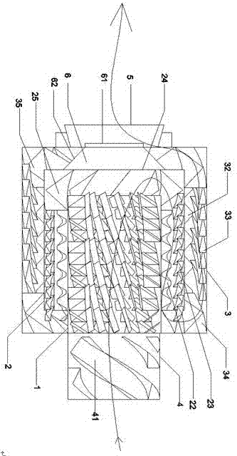
[0025] The present invention will be further described below in conjunction with specific embodiments. In this embodiment, the passage between the inner cylinder 1 and the middle cylinder 2 is called the middle cylinder flow channel; the passage between the middle cylinder 2 and the outer cylinder 3 is called Outer barrel runner.

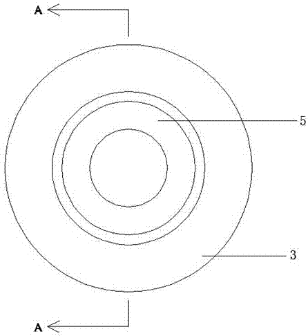
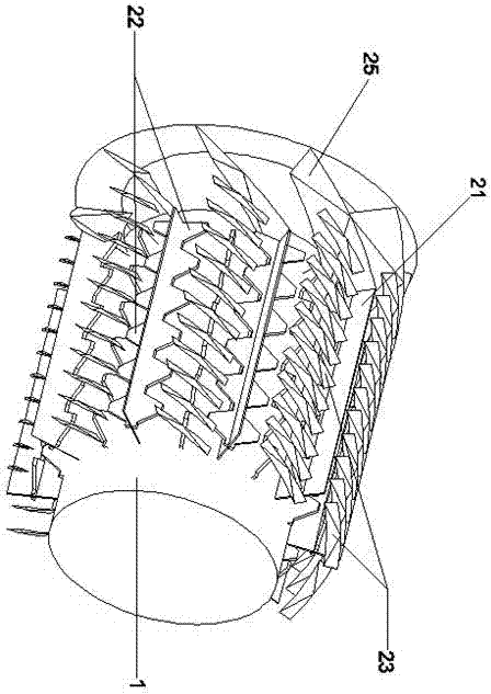
[0026] An embodiment of a sawtooth sand raising plate type sand drying machine provided by the present invention, such as figure 1 , figure 2 and image 3 As shown, the inner cylinder 1 is included, the outer coaxial sleeve of the inner cylinder 1 is provided with the middle cylinder 2, the outer coaxial sleeve of the middle cylinder 2 is provided with the outer cylinder 3, the feeding end of the inner cylinder 1 is provided with the feeding cylinder 4, and the outer cylinder 3 The discharge end is provided with a circumscribed cone 5, which is characterized in that: an inner cylinder sand blowing composite plate is provided on the inner wall of ...


PUM


Abstract

The invention discloses a sawtooth-shaped sand raising plate type sand drying machine. The machine comprises an inner cylinder, a middle cylinder and an outer cylinder, wherein the inner cylinder, themiddle cylinder and the outer cylinder are coaxially sleeved with one another from inside to outside; the feeding end of the inner cylinder is provided with a feeding cylinder, the discharging end ofthe outer cylinder is provided with an external connection cone, an inner cylinder sand raising combined plate is arranged on the inner wall of the inner cylinder, a middle cylinder partition plate and a middle cylinder sand sliding plate are arranged between the inner cylinder and the middle cylinder in the axial direction, the two sides of the middle cylinder partition plate are arranged on theouter wall of the inner cylinder and the inner wall of the middle cylinder correspondingly, middle cylinder sand raising plates are arranged on the two sides of the middle cylinder partition plate, the middle cylinder sand sliding plate is arranged on the inner wall of the middle cylinder, and a middle cylinder baffle plate is arranged at the discharging end of the middle cylinder; an outer cylinder partition plate and an outer cylinder sand sliding plate are arranged between the middle cylinder and the outer cylinder in the axial direction, the two sides of the outer cylinder partition plateare arranged on the outer wall of the middle cylinder and the inner wall of the outer cylinder correspondingly, outer cylinder sand raising plates are arranged on the two sides of the outer cylinderpartition plate, and the outer cylinder sand sliding plate is arranged on the inner wall of the outer cylinder. According to the machine, in the middle cylinder and the outer cylinder, most hot air can be effectively acted on the thrown wet sand, the effective heat exchange area of sand and hot air is increased, the damp and hot moisture in the sand is taken away, and the energy consumption loss is reduced.

Description

technical field [0001] The invention relates to construction dry powder ready-mixed mortar process equipment, in particular to the field of wet sand drying process equipment, and in particular to a sawtooth sand raising plate type sand oven. Background technique [0002] As we all know, compared with the single-pass sand drying machine, the three-pass sand drying machine occupies a small area. Under the same output, the occupied area is one-third of that of the single-pass sand drying machine. The inner hot gas rotary channel is convenient for heat collection in the inner ring, with low energy consumption, high output and good material drying effect. However, the traditional three-pass sand drying machine. Moreover, the middle cylinder and the outer cylinder are single-law sliding sand boards, and the speed of the quicksand is the same, and the performance of shedding moisture is not good, which affects the stability of production capacity. Contents of the invention [0...

Claims


Application Information

Patent Timeline
Patent Type & Authority Applications(China)
IPC IPC(8): F26B17/34F26B25/16F26B25/04
CPCF26B17/34F26B25/04F26B25/16F26B2200/14
Inventor 董青山毛伟强王飞宋海亮丁岩李岩赵红君张朝袁科龙张国梁
Owner ZHENGZHOU TONGDING MASCH EQUIP CO LTD
Learn More