Manufacture method of intelligent bus card

A technology of an intelligent bus card and a manufacturing method, which is applied to record carriers, instruments, computer parts and other directions used by machines, can solve the problems of bus IC card shell breakage, small size of bus IC card, and bending and bending, etc. Good tightness, avoid metal fatigue, reduce the effect of distortion

Inactive Publication Date: 2018-05-04
范亦能
View PDF0 Cites 0 Cited by
  • Summary
  • Abstract
  • Description
  • Claims
  • Application Information

AI Technical Summary

Problems solved by technology

[0003] When most passengers use bus IC cards, they usually carry them with them and put them in their trouser pockets or wallets for easy use; however, due to their small size and thin thickness, bus IC cards are easy to lose or be bent when carrying them. , which in turn causes the bus IC card shell to break and the chip in the card to be damaged

Method used


Image

  • Manufacture method of intelligent bus card

Examples


Embodiment 1

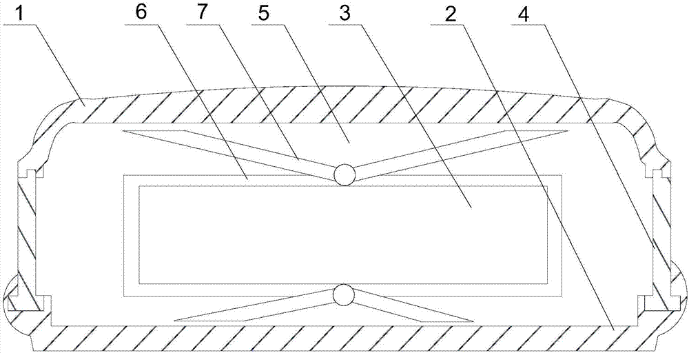
[0025] like figure 1 As shown, this embodiment includes the following steps:

[0026] (A) forming an upper shell 1 and a lower shell 2 capable of engaging with each other by injection molding in a mold;

[0027] (B) A support body 6 is fixedly installed in the lower casing 2, a chip 3 is placed in the support body 6, and a filler 5 is arranged around the support body 6, and the chip 3 is placed at the center of the lower casing 2;

[0028] (C) A V-shaped metal frame 7 is hingedly connected to the upper and lower ends of the support body 6, and a gap is left between the movable end of the V-shaped metal frame 7 and the upper shell 1 and the lower shell 2 respectively;

[0029] (D) The upper casing 1 and the lower casing 2 are connected and matched by the rubber block 4, and then the upper casing 1 and the lower casing 2 are bonded and sealed by an adhesive.

[0030] The work of the present invention is an improvement to the existing bus IC card shell, and the upper casing 1, ...

Embodiment 2

[0033] like figure 1 As shown, this embodiment is based on Embodiment 1. In step (C), the two V-shaped metal frames 7 are symmetrically arranged on the top and bottom surfaces of the support body 6 with the cavity as the center. Two V-shaped metal frames 7 are symmetrically arranged on the support body 6 with the cavity as the center, so that when the front or back of the IC card or the left end or the right end is subjected to external force, the V-shaped metal frame 7 can make the same direction. Deformation reaction to reduce the degree of distortion of the card surface and avoid damage to the chip 3 in the support body 6 .

[0034] Preferably, the filler 5 is foamed plastic. The foamed plastic is light in weight and has good tightness. When it is filled into the cavity together with the V-shaped metal frame 7, it can ensure that the V-shaped metal frame 7 is provided with a certain support, and at the same time, it can also make the V-shaped bracket deform freely, avoidin...


PUM


Abstract

The invention discloses a manufacture method of an intelligent bus card. The method includes the following steps that (A) an upper shell body and a lower shell body which can be meshed with each otherare formed in a die in an injection molding mode; (B) a support body is fixedly mounted in the lower shell body, a chip is placed in the support body, filler is arranged around the support body, andthe chip is placed at the center of the lower shell body; (C) V-shaped metal racks are in respective hinged connection with the upper end and the lower end of the support body, and gaps are respectively reserved between the moving end of one V-shaped metal rack and the upper shell body and between the moving end of the other V-shaped metal rack and the lower shell body; and (D) the upper shell body and the lower shell body are connected and matched through a rubber block, and then the upper shell body and the lower shell body are bonded and sealed through adhesives. The two moving ends of theV-shaped metal racks are deformed around hinged points on the support body in a stress direction, thus entire-card-face distortion caused by external force is lightened, and then a phenomenon that theIC card is excessively distorted, and thus the chip is damaged is avoided.

Description

technical field [0001] The invention relates to the field of mobile communication, in particular to a manufacturing method of an intelligent bus card. Background technique [0002] IC card refers to integrated circuit card. The bus card we generally use is a kind of IC card. Generally, common IC cards use radio frequency technology to communicate with IC card readers. There is a difference between IC cards and magnetic cards. The card stores information through the integrated circuit in the card, while the magnetic card records information through the magnetic force in the card. The cost of the IC card is generally higher than that of the magnetic card, but the confidentiality is better. The bus IC card is a kind of non-contact data card, it is through the chip integrated in the card through the inductance coil on the card (the inductance coil is also a coil made of copper wire) at both ends of the coil through various The function of the circuit makes the induced current b...

Claims


Application Information

Patent Timeline
Patent Type & Authority Applications(China)
IPC IPC(8): G06K19/077B29C69/00
CPCG06K19/07718B29C69/00G06K19/07724G06K19/07728
Inventor 范亦能
Owner 范亦能
Why Eureka
Try Eureka