Lighting and energy-saving control device

A control device, energy-saving control technology, applied in the direction of circuit devices, battery circuit devices, transportation and packaging, etc., can solve problems such as single function, large amount of dust accumulation, complex structure, etc., to reduce the use cost, relieve economic pressure, improve The effect of service life

Pending Publication Date: 2018-05-04
ZHEJIANG UNIV OF TECH
View PDF5 Cites 2 Cited by
  • Summary
  • Abstract
  • Description
  • Claims
  • Application Information

AI Technical Summary

Problems solved by technology

[0003] However, the lighting energy-saving control devices currently on the market have complex structures and single functions. Since there are many control elements installed inside the lighting energy-saving control devices, when these control elements work normally, part of the electric energy will be converted into heat energy. If the heat cannot be discharged in time To the outside of the lighting energy-saving control device, it will affect the normal use of the lighting energy-saving control device and shorten the normal service life of the lighting energy-saving control device; in addition to generating heat energy, the internal control components of the lighting energy-saving control device will also produce electrostatic adsorption. It will inhale the dust floating in the environment to the surface of the control components. Over time, the accumulation of dust will become larger and larger, which will also affect the normal work of the lighting energy-saving control device; impact, causing damage to the shell of the lighting energy-saving control device

Method used


Image

  • Lighting and energy-saving control device
  • Lighting and energy-saving control device

Examples


Embodiment

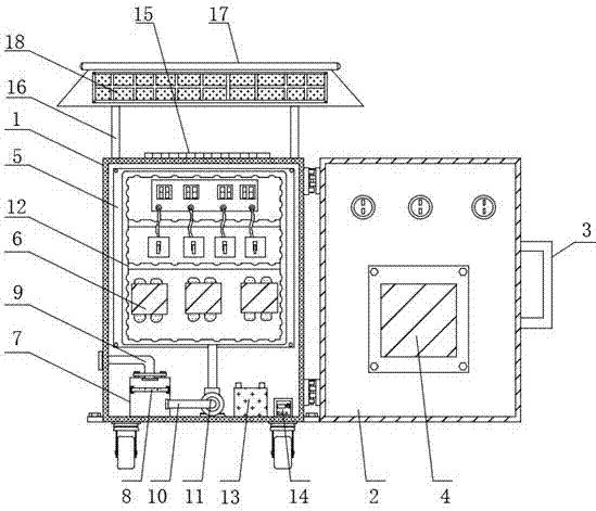
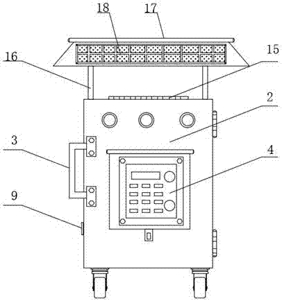
[0022] Example: such as Figure 1-2 As shown, the present invention provides a technical solution, a lighting energy-saving control device, including a control device body 1, an inspection door 2 that is rotatably connected to the control device body 1 is provided on one side of the control device body 1, and the rear surface side of the inspection door 2 is fixedly installed. There is a handle 3, and a control switch 4 is fixedly embedded on the side of the rear surface of the inspection door 2 close to the handle 3, a fixed plate 5 is fixedly installed on the inner wall of the control device body 1, and a control switch is fixedly installed on the front surface of the fixed plate 5. Component 6, the inner bottom end of the control device body 1 is fixedly equipped with a treatment box 7, the interior of the treatment box 7 is provided with a filter screen 8 slidingly connected to it, and the upper surface of the treatment box 7 is fixedly provided with a first dust delivery p...


PUM


Abstract

The invention discloses a lighting and energy-saving control device. The lighting and energy-saving control device comprises a control device body and a maintenance door, wherein a control switch is arranged on the maintenance door, a fixed plate, a processing box, an exhaust fan, a storage battery and an inverter are arranged in the control device body, a group of control components are arrangedon the fixed plate, a filtering net is arranged in the processing box, the processing box is connected with a first smoke transmission pipe and a second smoke transmission pipe, the other end of the second smoke transmission pipe is connected with the exhaust fan, a dust collection pipe is fixedly arranged at an upper end of the exhaust fan, a trapezoid protection shed is arranged at the top of the control device body, and a photovoltaic solar cell panel is arranged on the trapezoid protection shed. By members such as the exhaust fan, the processing box and the filtering net, heat is rapidly dissipated when the lighting and energy-saving control device normally works; and meanwhile, dust and air are sucked to the processing box, the dust is filtered by the filtering net, and the device canbe prevented from being affected by an external environment to be damaged by the trapezoid protection shed.

Description

technical field [0001] The invention relates to the technical field of energy-saving devices, in particular to a lighting energy-saving control device. Background technique [0002] Lighting energy-saving control device is a high-tech intelligent power-saving and energy-saving product. It is different from general power-saving devices and voltage stabilizers. It is guided by modern control theory and adopts the most advanced industrial The control computer and special microcomputer optimize the voltage of the lighting power supply system. [0003] However, the lighting energy-saving control devices currently on the market have complex structures and single functions. Since there are many control elements installed inside the lighting energy-saving control devices, when these control elements work normally, part of the electric energy will be converted into heat energy. If the heat cannot be discharged in time To the outside of the lighting energy-saving control device, it w...

Claims


Application Information

Patent Timeline
Patent Type & Authority Applications(China)
IPC IPC(8): H05K7/20H02J7/35
CPCH02J7/35H05K7/20172H05K7/20181Y02E10/56
Inventor 周明珏李美艳李曰兵
Owner ZHEJIANG UNIV OF TECH
Why Eureka
Try Eureka