Supercharge Your Innovation With Domain-Expert AI Agents!

Cooling type industrial waste gas treatment device

A technology for industrial waste gas and treatment devices, which is applied in gas treatment, fixed conduit components, dispersed particle filtration, etc., can solve the problems of affecting the life safety of surrounding people, difficult to develop sustainable roads, and consume large amounts of energy. Increased service life and small footprint

Inactive Publication Date: 2018-05-08
QUANZHOU HUIAN MINTOU TRADING CO LTD
View PDF4 Cites 3 Cited by
  • Summary
  • Abstract
  • Description
  • Claims
  • Application Information

AI Technical Summary

Problems solved by technology

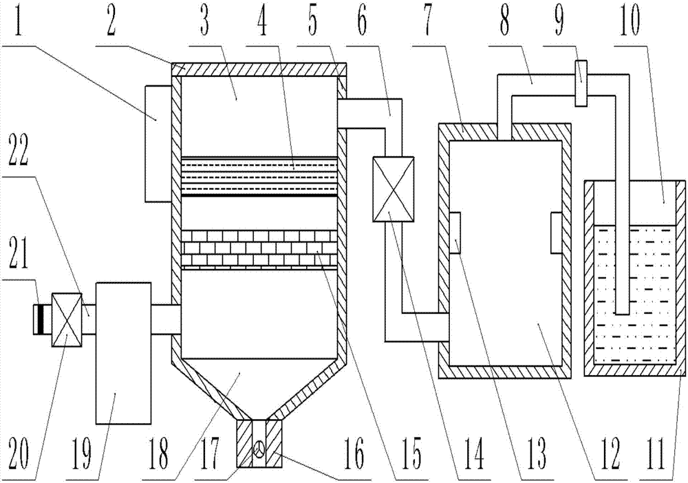
[0002] In the process of chemical manufacturing, a large amount of waste gas is usually produced. Usually, the waste gas contains a lot of impurities and toxic substances. If these impurities and toxic substances cannot be treated well, they will be directly discharged into the air, which will pollute the air, and then Affect the lives and safety of the surrounding people; although the traditional waste gas treatment device has a high filtering effect, it cannot decompose and remove harmful substances in the waste gas. There are also large-scale industrial waste gas treatment devices that can react to harmful substances and then filter and remove them. , but the volume is too large, it is not easy to move, occupies a large area, consumes a lot of energy, and is not easy to follow the road of sustainable development; therefore, a convenient and practical industrial waste gas treatment device is needed

Method used


Image

  • Cooling type industrial waste gas treatment device
  • Cooling type industrial waste gas treatment device
  • Cooling type industrial waste gas treatment device

Examples


Embodiment Construction

[0016] The technical solution of this patent will be further described in detail below in conjunction with specific embodiments.

[0017] Embodiments of the present patent are described in detail below, examples of which are shown in the drawings, wherein the same or similar reference numerals designate the same or similar elements or elements having the same or similar functions throughout. The embodiments described below by referring to the figures are exemplary and are only used for explaining the patent, and should not be construed as limiting the patent.

[0018] In the description of this patent, it is to be understood that the terms "center", "upper", "lower", "front", "rear", "left", "right", "vertical", "horizontal", The orientation or positional relationship indicated by "top", "bottom", "inner", "outer", etc. is based on the orientation or positional relationship shown in the drawings, and is only for the convenience of describing this patent and simplifying the des...


PUM


Abstract

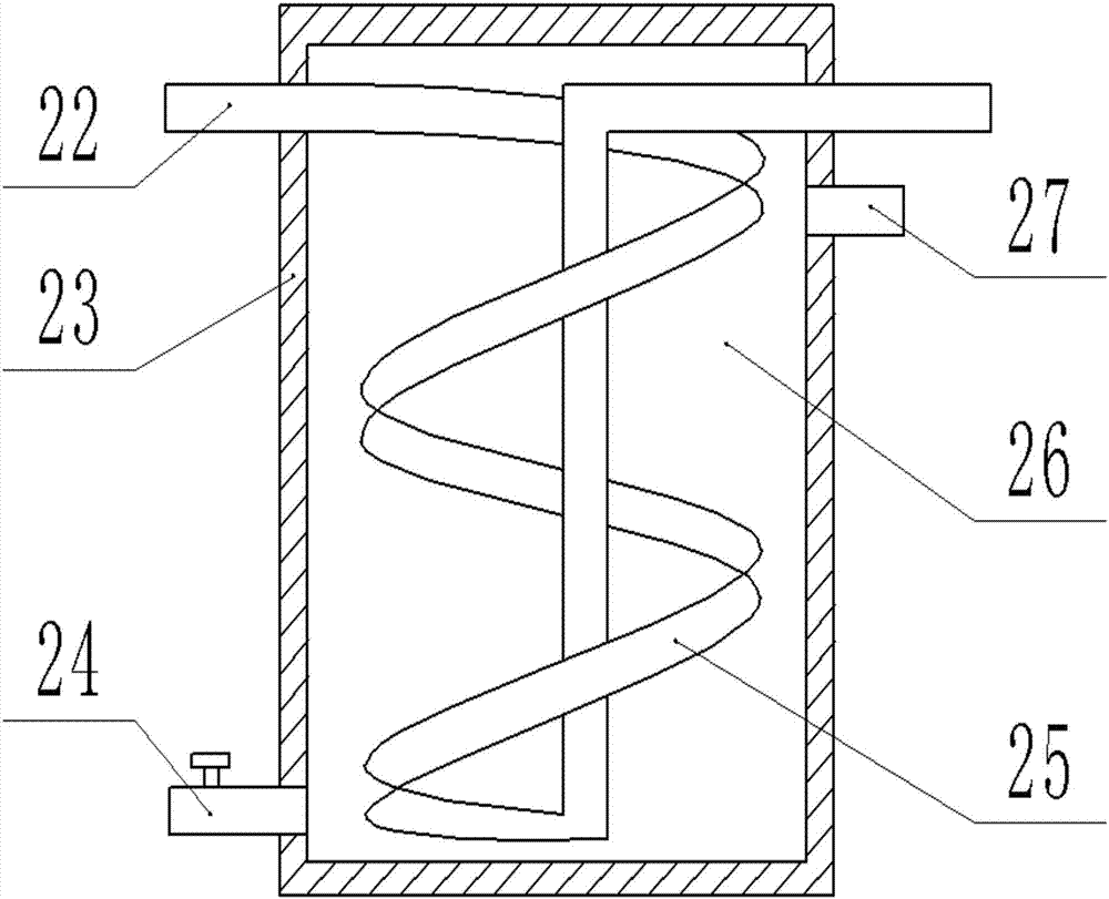
The invention provides a cooling type industrial waste gas treatment device, and belongs to the field of waste gas treatment device; the cooling type industrial waste gas treatment device includes a shell, a reaction cavity and a cooling device; the shell is shaped as a cylinder and is vertically placed, and a filter cavity and a collection cavity are arranged inside the shell; the filter cavity is arranged at the upper end of the collection cavity, and the upper end of the filter cavity is provided with an end cover; the end cover is connected with the shell in a thread manner; a first filterplate is located at the upper side and contains active carbon; a second filter plate is provided with a fine filter screen; a gas inlet pipe is arranged below the left end of the filter cavity in a connection manner; the cooling device is arranged at the right end and the filter screen is arranged at the left end; the collection cavity is in a funnel shape; a valve is arranged inside a blowdown device; the right end of the filter cavity is provided with a reaction box, a connecting pipe is arranged between the reaction box and the shell in a fixed-connection manner, and the connecting pipe isprovided with a second air blower in a connection manner. The cooling type industrial waste gas treatment device has the advantages of simple structure, convenient use, small land occupation area, good waste gas treating effect and high efficiency.

Description

technical field [0001] The invention relates to a waste gas treatment device, in particular to a cooling industrial waste gas treatment device. Background technique [0002] In the process of chemical manufacturing, a large amount of waste gas is usually produced. Usually, the waste gas contains a lot of impurities and toxic substances. If these impurities and toxic substances cannot be treated well, they will be directly discharged into the air, which will pollute the air, and then Affect the lives and safety of the surrounding people; although the traditional waste gas treatment device has a high filtering effect, it cannot decompose and remove harmful substances in the waste gas. There are also large-scale industrial waste gas treatment devices that can react to harmful substances and then filter and remove them. , but the volume is too large, it is not easy to move, occupies a large area, consumes a lot of energy, and is not easy to follow the road of sustainable develop...

Claims


Application Information

Patent Timeline
Patent Type & Authority Applications(China)
IPC IPC(8): B01D53/04B01D46/12B01D53/00F28D1/047
CPCB01D46/12B01D53/007B01D53/04B01D2253/102B01D2257/91B01D2259/804F28D1/0472
Inventor 侯芬芳
Owner QUANZHOU HUIAN MINTOU TRADING CO LTD
Features
  • R&D
  • Intellectual Property
  • Life Sciences
  • Materials
  • Tech Scout
  • Unparalleled Data Quality
  • Higher Quality Content
  • 60% Fewer Hallucinations
Learn More