Hoop-bending device for stainless steel pipes

A technology of stainless steel and bending hoops, which is applied in the field of stainless steel pipe bending hoops, can solve the problems of reducing processing procedures and inconvenient picking up parts, and achieves the effect of reducing processing procedures and solving inconvenient picking up parts

Active Publication Date: 2018-05-08
华汉致信(宁波)供应链管理有限公司
View PDF5 Cites 2 Cited by
  • Summary
  • Abstract
  • Description
  • Claims
  • Application Information

AI Technical Summary

Problems solved by technology

[0005] The technical effect of this scheme is: through the cooperation of the No. 1 rack, the No. 1 gear and the No. 2 gear, the No. 1 bending hoop block and the No. 2 bending hoop block are driven to move up and down, and at the same time cooperate with the bending hoop groove to carry out the stainless steel pipe middle part. Bending hoop processing; the pulley moves with the No. 1 rack. During the movement, the position of the pulley changes and cooperates with the No. 1 gear, the No. 2 gear, the No. 1 stay rope and the No. 2 stay rope to realize the No. The rotation of the No. 1 bending hoop plate realizes the bending hoop processing at both ends of the stainless steel pipe; the No. 1 bending hoop block and the No. 2 bending hoop block move downward while cooperating with the hole-opening nails, which can open holes for the stainless steel pipe and reduce the follow-up At the same time, the cavity formed by the No. 1 bend hoop block and the No. 2 bend hoop block can collect waste materials; and then cooperate with the electromagnet, the No. 3 gear and the material storage mechanism to realize the No. 1 bend hoop block and the No. 2 bend hoop The automatic unloading of hoop blocks effectively solves the problem of inconvenient pick-up, and at the same time, the stainless steel pipes and waste materials after bending hoops can be collected automatically

Method used


Image

  • Hoop-bending device for stainless steel pipes
  • Hoop-bending device for stainless steel pipes
  • Hoop-bending device for stainless steel pipes

Examples


Embodiment Construction

[0014] Further detailed explanation through specific implementation mode below:

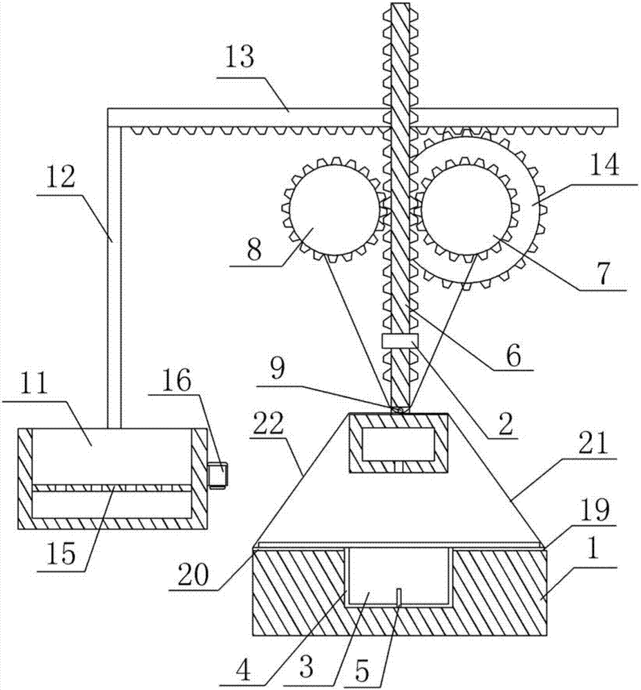
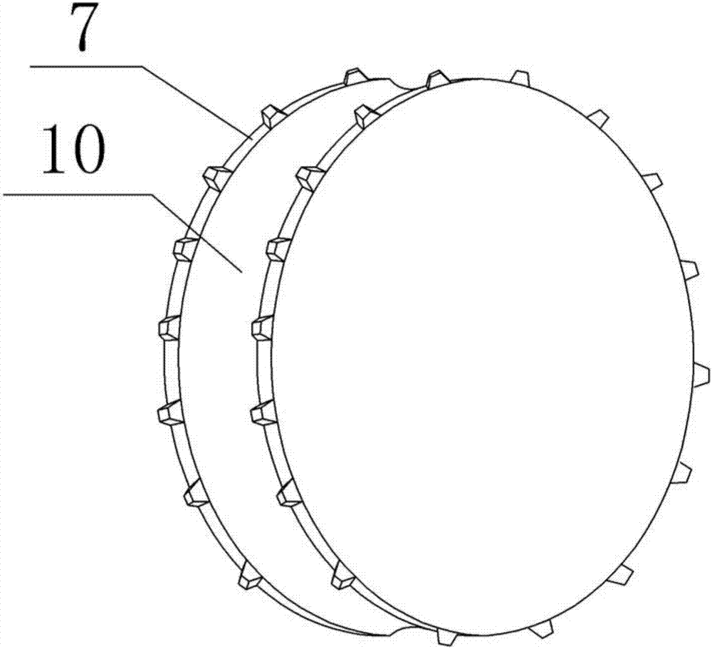
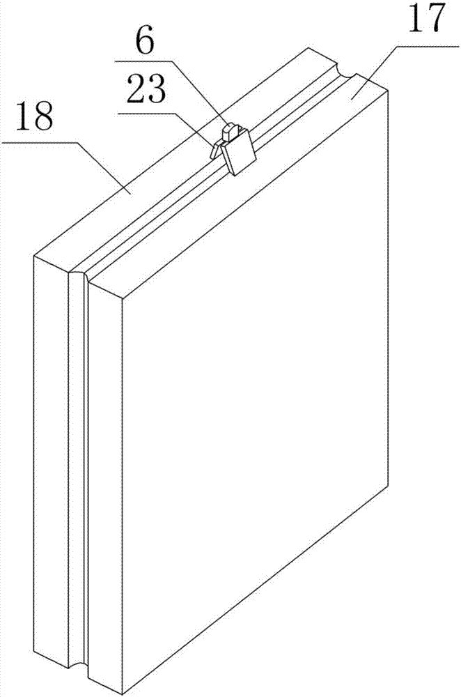
[0015] The reference signs in the accompanying drawings of the specification include: support platform 1, electromagnet 2, bending hoop groove 3, arc groove 4, hole nail 5, rack number one 6, gear number one 7, gear number two 8, pulley 9. Annular groove 10, storage box 11, support rod 12, No. 2 rack 13, No. 3 gear 14, grid 15, vibration motor 16, No. 1 bending hoop block 17, No. 2 bending hoop block 18, No. 1 Bending hoop plate 19, No. 2 bending hoop plate 20, No. 1 stay cord 21, No. 2 stay cord 22, distance-expanding block 23.

[0016] Such as figure 1 The stainless steel pipe hoop bending device shown includes a supporting platform 1, a hoop bending mechanism, an electromagnet 2, a removal mechanism and a material holding mechanism from bottom to top. Bending hoop groove 3 is arranged on the supporting platform 1, and the groove wall and groove bottom of bending hoop groove 3 are provided wi...


PUM


Abstract

The invention relates to the field of hardware processing, in particular to a hoop-bending device for stainless steel pipes. The hoop-bending device comprises a supporting table, a removing mechanism,a storing mechanism, a hoop-bending mechanism and an electromagnet. A hoop-bending groove is formed in the supporting table, and a trepanning nail is fixed to the bottom of the hoop-bending groove. The removing mechanism comprises a first rack, a first gear and a second gear. The storing mechanism comprises a storing box, a supporting rod, a third gear and a second rack. The hoop-bending mechanism comprises a first hoop-bending plate, a second hoop-bending plate, a first pull rope, a second pull rope, a first hoop-bending block and a second hoop-bending block. When the technical scheme is adopted, waste collecting and automatic unloading are achieved while the stainless steel pipes are subjected to hoop-bending treatment.

Description

technical field [0001] The invention relates to the field of hardware processing, in particular to a stainless steel pipe bending hoop device. Background technique [0002] In hardware manufacturing, the manufacture of stainless steel pipes is very common, and in many cases it is necessary to bend the stainless steel pipes. Generally, manual bending hoops are used. Because the rigidity of stainless steel pipes is relatively good, it is not easy to complete the bending hoops by manual operation, and each stainless steel pipe needs to be bent several times, so it takes a lot of time and the bending hoops are very efficient. Low. Therefore, at present, electric hoop bending machines are usually used to bend stainless steel pipe hoops, which saves labor and improves the efficiency of hoop bending. However, the existing hoop bending machine still has the following disadvantages: the stainless steel pipe after bending hoop cannot be automatically unloaded, and it is not easy to ...

Claims


Application Information

Patent Timeline
IPC IPC(8): B21D7/06B21D7/16B21D45/00
CPCB21D7/06B21D7/16B21D45/00
Inventor 邱红光
Owner 华汉致信(宁波)供应链管理有限公司
Why Eureka
Try Eureka